
A 1 mm thin-wall robot dexterous hand frame cannot be made stable by simply tightening tolerances or using a finer tool path. Low stiffness means clamping force, cutting force, chip heat and surface treatment can all amplify deformation.
A part may measure correctly on the machine and then shift after release. Hole position, flatness and profile size can change once the fixture no longer holds the thin structure.
OEMach usually starts these projects with a DFM review that marks the thinnest walls, assembly datums, allowed deformation and inspection method before selecting roughing, semi-finishing, finishing and deburring steps.
Control Points for 1 mm Thin-Wall Robot Hand Frames
| Control point | Main risk | Process suggestion | Acceptance focus |
|---|---|---|---|
| Clamping method | Part measures correctly while clamped but springs back after release | Use soft jaws, formed fixtures, vacuum assist or local support | Measure in free state, not only in clamped state |
| Stock removal sequence | One-sided cutting causes warpage | Use balanced removal, staged machining and rough-finish separation | Profile, wall thickness and flatness together |
| Cutting force | Vibration, tool deflection and more burrs in thin zones | Use sharp small tools, light depth of cut and multiple passes | Hole-mouth burrs, edge deformation and surface marks |
| Datum protection | Early operations damage later locating faces | Keep stable datum surfaces before cutting thin features | Relationship between holes and mounting faces |
| Surface treatment | Blasting or anodizing changes size and appearance | Mask key holes when needed and inspect after treatment | Coating thickness, bore size and mounting face condition |
Control Deformation Before Chasing Size
The main difficulty of a thin dexterous hand frame is not whether the tool can reach the contour. The part has low stiffness, so every support point and every tool pass can change its free-state geometry.
Before quoting or programming, the drawing should clarify minimum wall thickness, functional holes, mounting faces, allowed deformation and inspection method. Without this, high tolerance notes may be applied to surfaces that do not control assembly.
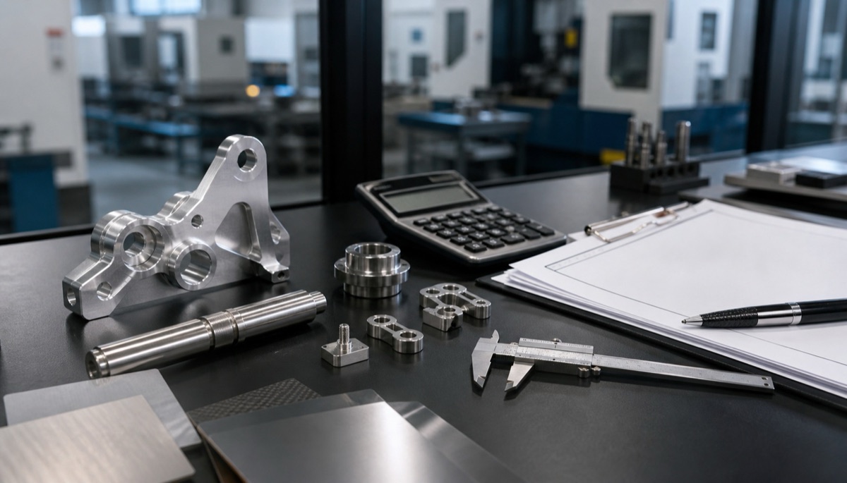
Why 1 mm Thin Walls Need Functional Tolerance Zones
A 1 mm thin-wall structure should not use one precision level across the whole drawing. Appearance contours can often be relaxed, while locating holes, datum steps and mounting faces need tighter dimensional and geometric control.
OEMach separates the part into datum and assembly surfaces, load or motion related areas, and lightening or appearance areas. The first two groups receive the clearest tolerances and inspection datums. The last group is optimized for weight, burr control and practical machining.
Recommended Machining Route
Roughing should remove major stock while leaving safe allowance around critical thin walls. This lets stress release before the part reaches its final dimensions.
Semi-finishing then establishes one datum system and checks the relationship among holes, mounting faces and profile. During final thin-wall finishing, single-pass cutting force should be reduced, long tool overhang avoided and local heat kept under control.
Deburring and cleaning should be managed as their own steps. A 1 mm edge can be damaged by an oversized chamfer or by burrs left in an assembly gap.
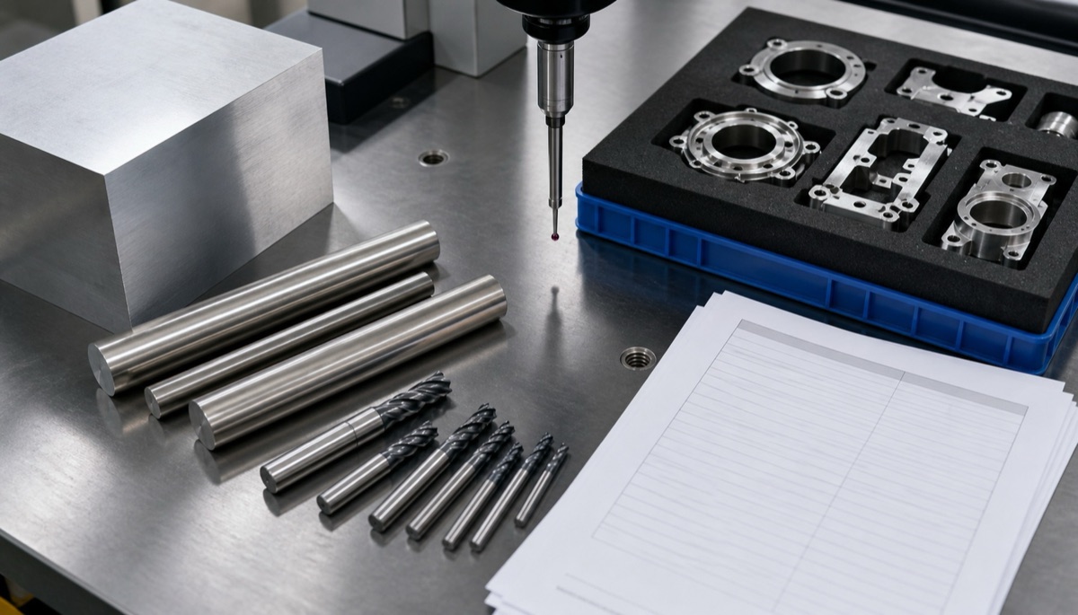
Check the Part After Release
For thin robot components, the clamped condition can be misleading. A free-state check is needed for key dimensions, flatness, hole position and assembly datums.
If the customer has a mating frame, pin or simulated gauge, using it during first-article review helps confirm whether the part is only dimensionally acceptable or truly assembly-ready.
How Procurement Can Reduce Risk
A good RFQ should include the 3D model, 2D critical tolerances, wall-thickness notes, assembly sketch, surface treatment requirement and first-article verification method.
For prototype and small-batch projects, a supplier that can review thin-wall risks, fixture concepts and measurement records is more useful than one that only quotes from nominal machine accuracy.
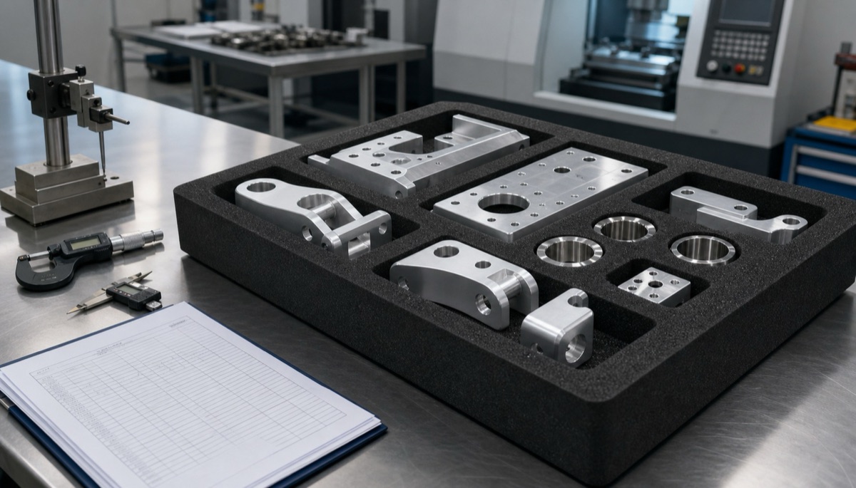
Common Mistakes
The first mistake is treating a 1 mm frame like a normal sheet-metal or plate part. A dexterous hand frame has holes, slots, steps and datums that create more complicated deformation paths.
The second is specifying only size tolerance while ignoring flatness, perpendicularity and hole-position datums. The third is underestimating deburring, where a too-large chamfer or remaining burr can change motion clearance.
Summary
The key to machining a robot dexterous hand frame is controlling clamping, stock removal and datum drift before trusting final dimensions. When the design team provides wall thickness, assembly faces, deformation allowance and inspection method, the supplier can turn a machinable sample into a repeatable small-batch part.
FAQ
Can a 1 mm thin-wall robot part hold ±0.005 mm?
Some critical features may approach high precision with stable fixturing and inspection, but a full drawing-wide ±0.005 mm requirement is usually not practical for 1 mm thin walls.
Why do thin-wall parts change size after unclamping?
Clamping and cutting forces elastically deform low-stiffness structures. After release, the part springs back and changes dimension or geometric relationship.
What materials suit robot dexterous hand frames?
Common choices include 6061, 7075 and stainless steel. The decision depends on weight, strength, surface treatment and assembly requirements.
Why do small-batch thin-wall quotes vary so much?
The difference often comes from fixtures, setup, tools, deburring, inspection and surface-treatment risk, not only material cost.
Can OEMach support 1 mm thin-wall prototypes?
Yes. OEMach can review thin-wall CNC routes, clamping strategy and inspection focus based on drawings and prototype requirements.
Ready to get a quote for your CNC machined parts?
Submit your engineering drawings to qiancj@oemach.com. We support prototype sampling and small-batch production with strict tolerance control.