
Distinguish a lead nut from a complete motion system
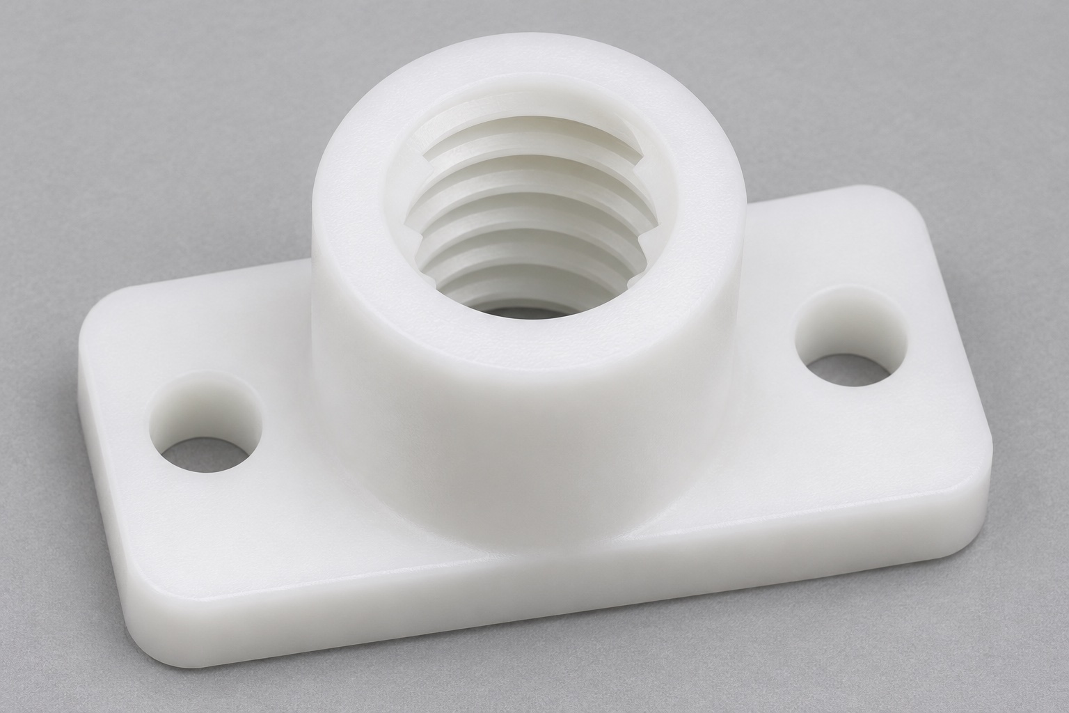
A medical analyzer may use a lead screw mechanism for a nonclinical positioning function inside its equipment. This article concerns the machined nut body and its drawing interfaces, not the accuracy or approval of the complete analyzer. The illustrative concept is one white POM-C component with a rectangular mounting flange, a central cylindrical boss, one axial internal trapezoidal through thread and two plain mounting holes. It has no split body, spring preload or ball recirculation. Before machining is discussed, identify the actual screw, support arrangement, mounting surface and approved component revision.

Specify more than a nominal thread diameter
A useful thread definition identifies the profile, nominal size, pitch, lead, number of starts, handedness and applicable acceptance requirements. Pitch and lead should not be treated as interchangeable without checking the design. A thread that appears to fit the diameter can still be wrong for the intended screw. State the required designation directly on the drawing and identify the mating screw revision where relevant. Do not infer an ACME, trapezoidal or other profile from an illustration. The component shown here is a conceptual trapezoidal lead nut, not a released thread specification.
Define the mounting face and thread-axis relationship
The flange mounting face and the internal thread axis form an important interface pair. The drawing should describe their required relationship and identify the references used for inspection. Two plain mounting holes alone do not establish how the nut is aligned within the mechanism; clearance, locating features and the mounting procedure must also be known. A bolt pattern that measures correctly in isolation may still be unsuitable if the thread axis is not related to the intended assembly references. Record those relationships before choosing how the part will be held or measured.
Choose POM-C from a controlled material requirement
Confirm the specified polymer grade, stock form, color and documentation rather than treating all white acetal as equivalent. Manufacturer machining guidance can inform process planning, but it does not establish suitability for a particular medical application. The intended cleaning agents, operating environment and contact classification require their own assessment. Review stock history and the amount of material to be removed when planning the operation sequence. No biocompatibility, sterilization compatibility, permitted load or lifetime can be assigned to a machined lead nut merely from the name POM-C or its color.
Support the flange without distorting the boss
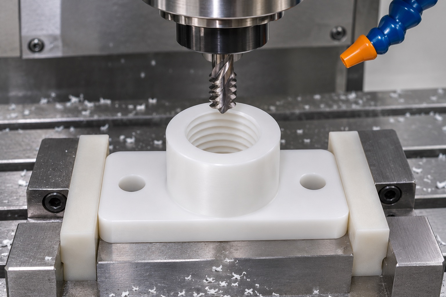
Workholding should support the part in a way that preserves the geometry being accepted after release from the fixture. Broad support under the flange may be preferable to concentrating force on a narrow edge, but the actual setup must follow the component design and machine access. Clamping force should not be chosen solely to prevent visible movement. The process review should consider whether fixture pressure could affect the thread bore or mounting face. Measurement after unclamping is a separate step from observing that a component remained secure during a machining pass.
Plan the thread operation and chip escape
The manufacturing plan should identify how the internal thread will be produced and how the tool enters and exits the through bore. Tool access, engagement length, chip removal and the two bore entrances need review before production. A through hole does not guarantee that every fragment will leave the thread roots without cleaning. Avoid prescribing a universal cutting speed or lubrication practice without considering the polymer grade and actual machine conditions. Any compatible process fluid and subsequent removal method should be part of the agreed route, with the finished thread protected from unnecessary repeated handling.
Keep plain mounting holes distinct from the threaded bore
The two flange holes in the concept are unthreaded mounting holes, not additional drive threads or lubricant ports. Their size, spacing and edge condition must come from the controlled drawing. Identify how the hole pattern relates to the thread axis and mounting face rather than measuring all dimensions from a cosmetic outside edge by habit. If countersinks, counterbores or locating dowels are required, they must be explicitly designed; they are not present in this illustration. A manufacturing change to the mounting pattern requires the same approval discipline as a change to the internal thread.
Separate thread acceptance from casual screw engagement
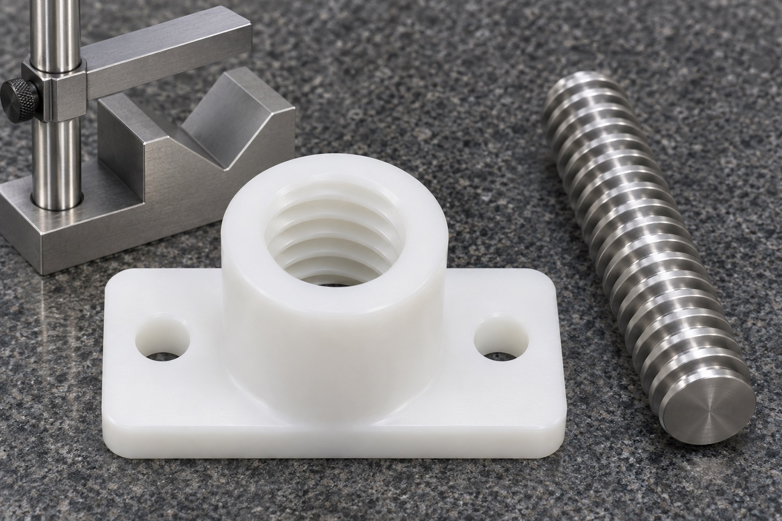
A mating screw sample can help investigate an assembly question, but a casual hand fit is not a complete thread inspection method. Define the intended gauges or measurement methods, acceptance criteria and condition of any checking screw. Identify whether the check concerns thread geometry, free passage or a specified assembly characteristic. Avoid using a worn development screw as an undocumented production master. Record the result against the actual component revision. The inspection illustration here shows no numerical reading, no go/no-go outcome and no evidence that a produced nut has passed any particular limit.
Review alignment at the mechanism level
Thomson's installation guidance identifies alignment and end support as relevant system considerations for lead screw arrangements. That background does not supply acceptance values for this illustrative nut. For the real mechanism, the equipment team should define how the screw, nut, guide and mounting surfaces are brought into alignment. Tightening the flange fasteners should not silently force a misaligned thread into place. Where an assembly observation is planned, record the actual components, fastening sequence and conditions. Unexpected resistance should lead to investigation of the interfaces before the nut is modified or the screw is forced through it.
Do not turn a one-piece nut into an anti-backlash claim
The concept contains one continuous nut body with no preload spring or separate adjustable elements. It therefore should not be marketed as a demonstrated anti-backlash mechanism. Motion behavior depends on the actual screw and nut geometry, installation, operating conditions and complete system evaluation. Dimensional conformity alone does not establish positioning accuracy, repeatability, load capability or service life. Those questions need their own defined tests and evidence. If the design changes to a split or preloaded assembly, its new interfaces and acceptance criteria should be reviewed as a different controlled configuration.
Clean and protect the internal thread
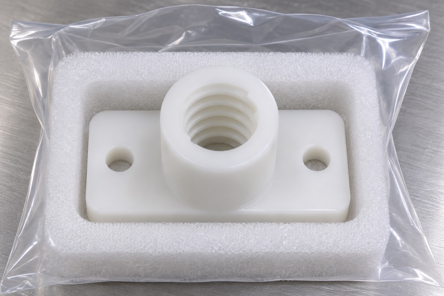
The cleaning plan should address chips retained in thread roots, residue at bore entrances and debris around the plain mounting holes. Select a method compatible with the specified material and intended use, then inspect the accessible features again after cleaning. Avoid inserting packaging plugs or identification tags that can leave fragments in the thread unless those items are approved. Separate finished parts so flange edges and threaded openings are not damaged in transit. Protective bags and clean handling do not establish sterile delivery, particle classification or suitability for contact with patient samples.
Prepare an inquiry that preserves thread identity
Provide the released drawing, model, quantity, material grade, complete thread designation, mating screw identification, mounting requirements and inspection deliverables. State any required operating observations separately from component dimensional checks, with an agreed procedure where necessary. Include cleaning and packaging expectations and identify any prohibited process fluids or residues. A useful quotation should explain assumptions that still need resolution rather than filling missing values with a generic motion-system claim. The generated images in this article illustrate a geometry and workflow only; they do not document a customer part, measured result or validated medical application.
Manufacturer background reference: www.thomsonlinear.com.
FAQ
Is this a ball screw nut?
No. The illustrated body is a one-piece POM-C lead screw nut with an internal trapezoidal through thread. It has no ball recirculation system. The complete thread specification and actual mating screw must be identified in the controlled design.
Are pitch and lead always the same?
They should not be assumed identical. The number of starts matters, and the drawing must identify the intended thread designation. A nominal diameter alone is insufficient to select a matching screw or define the thread acceptance method.
Does the concept include anti-backlash preload?
No. There is no split nut, preload spring or adjustment mechanism in the concept. No backlash, repeatability or positioning result is claimed. Any preloaded design would require its own controlled configuration and evaluation with the actual motion system.
Can a hand fit replace thread inspection?
Not by itself. Define the required gauges or other methods and their acceptance criteria. A checking screw should be identified and controlled. Casual engagement cannot establish all thread geometry or the operating behavior of the complete analyzer mechanism.
Does white POM-C imply medical approval?
No. The exact material grade, documentation, contact classification, cleaning agents and intended use require review. Color and polymer family alone do not establish biocompatibility, sterilization compatibility, sterile condition or approval of the finished device.
What should be provided for manufacturing review?
Supply the drawing and model revision, complete thread designation, quantity, POM-C grade, mating screw identification, flange references and required inspection records. Add cleaning, packaging and any separately defined assembly observations to avoid assumptions about motion performance.

tanghangyun@oemach.com