
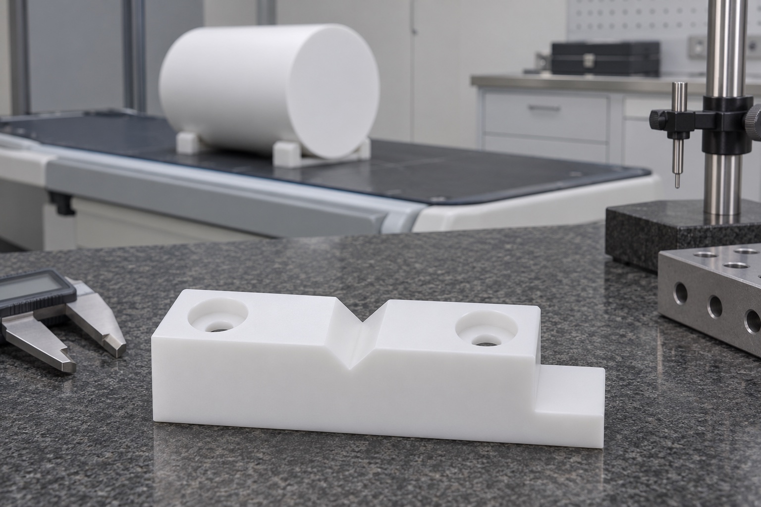
Start with the setup rather than the scan
An imaging quality assurance phantom is an object used to assess selected aspects of an imaging system. A removable locator can make the mechanical setup easier to reproduce, but it does not measure image quality or establish scanner acceptance. Define which phantom feature is to be located, where the fixture attaches and how the user recognizes full seating. Obtain the device owner's constraints on clearances and the imaging field before placing any material near it. The example discussed here is a bench concept and not a recommendation for a specific scanner.

Give each contact one job
A shallow V can locate the transverse position of a cylinder by contact on its two flanks. It does not by itself determine axial position, rotational orientation or the height of every possible cylinder. A defined end stop can locate axial position when it touches the specified end. If rotational orientation matters, an approved feature or external reference must handle it separately. Overconstraining the cylinder with extra pads can create rocking rather than stability. Draw the support scheme before deciding which surfaces need close tolerances.
Transfer the functional reference to the drawing
Define the mounting plane and any lateral reference from the actual table interface. The drawing should relate the contact flanks and end stop to those references. Position of counterbores alone does not define the position of the seated cylinder when fastener clearance permits movement. Where service access requires removable fasteners, a separate approved reference may be needed for lateral registration. Identify which dimensions the machining supplier can measure on the free fixture and which must be checked on the installed combination.
Account for diameter and contact zones
A cylindrical master of the wrong diameter contacts a V at different points and puts its center at a different height. A worn or out of round phantom can make measurements vary as it is turned. Define the size and condition of the master, and specify where along the cradle it is seated. Use enough points to detect twist between the two ends of a long groove. When a phantom has a seam, label, taper or local recess, confirm that none interferes with the intended seating lines.
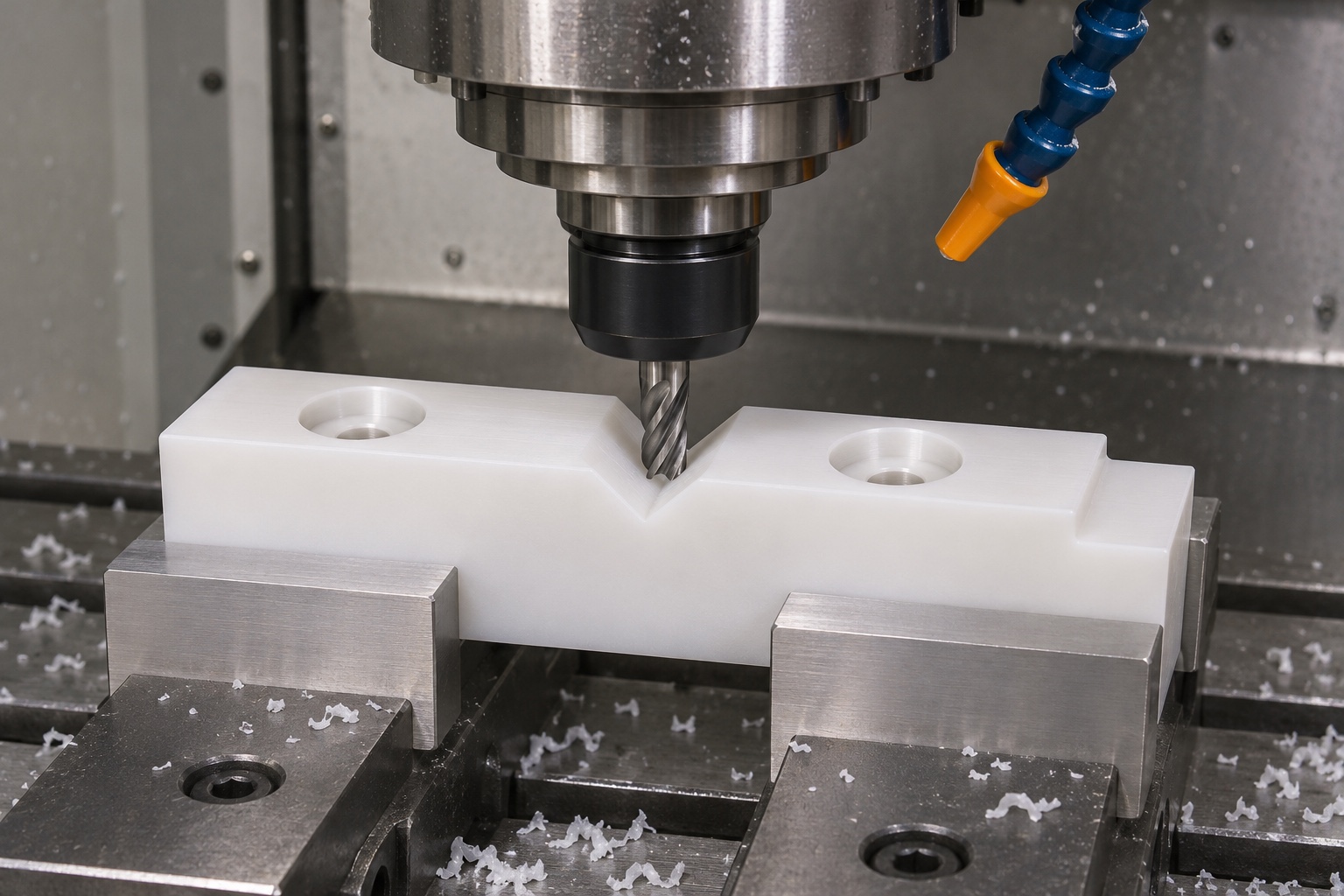
Pick material with the complete system in mind
Machinability and dimensional behavior are only part of material selection. A bench fixture may be practical in engineering plastic, but the final material, fasteners and coatings also depend on intended placement and owner review. Do not infer imaging compatibility from color, density alone or a photo. Confirm the expected storage and cleaning conditions and whether the locator remains installed during a scan. Any claim about artifacts or compatibility belongs to the owner of the approved assembly, not a dimensional report for a block.
Sequence the milling around the mounting plane
Face the blank to establish stable support, then rough the profile and recesses without clamping a thin region against a hard stop. Leave material where a second pass will establish the functional flanks. Consider releasing and reseating the part before finishing so that temporary clamping deformation is not machined into the part. Finish both flanks with controlled tool access and check that the tool radius at the root does not become an unintended third contact. Deburr the nonfunctional edges separately.
Inspect both geometry and seating
Geometry inspection can describe the relation between the mounting plane, groove flanks and stop. A seating trial addresses a different question: can a defined master be installed without rocking or touching a nonfunctional feature? Keep both results in the report. Identify the support condition, master identification and measuring method. A good seating trial cannot substitute for a called-out geometry result, and acceptable isolated dimensions do not prove that a flexible table, clamp or stop will behave the same way in the full assembly.
A practical drawing review starts with a simple question: could two inspectors set this part down in different ways and both believe they followed the drawing? For example, one may rest the locator on its underside while another uses its bolted orientation. Ask them to sketch the contacts independently. If the sketches disagree, define the support and orientation before agreeing the tolerance. Apply the same exercise to a cylindrical master. A suitable inspection drawing should make it clear where a reading begins, where it ends, and what evidence would be needed to compare one fixture with its replacement.
Design a repeatability study before collecting data
Compare multiple independent removals and reseats rather than repeating readings on an untouched fixture. Where operator influence is relevant, use a documented sequence and more than one trained operator. Observe axial movement and changes in height separately. Keep the individual readings and note cleaning, loading and orientation conditions; do not report only an average that could hide an occasional misseat. Choose trial sizes and criteria with the equipment owner. This mechanical exercise is not an imaging performance validation.
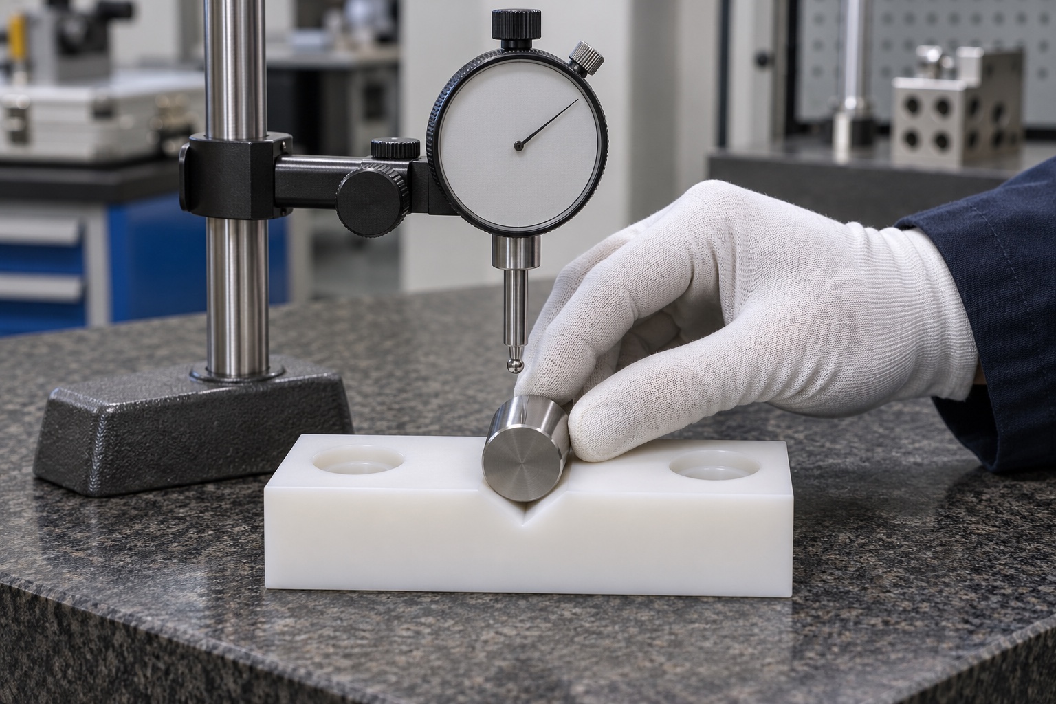
Make an incorrect setup easy to recognize
An asymmetrical profile or visible reference feature can help the operator recognize which end is forward. A handed marking alone is less useful if it is hidden when the phantom is placed. Use clearance studies to confirm that screws, cables and nearby housings cannot defeat the intended assembly sequence. If the tool will be removed before scanning, document the approved removal point and verify that removal does not disturb the located object. The device owner decides the approved operating procedure.
Keep cleaning separate from dimensional approval
Chips, adhesive and residue can change how the two flanks support the phantom. Specify which cleaning agents are compatible with both the block and surrounding equipment, and agree which areas must be free of debris. Inspect a machined edge without rounding a locating surface to conceal a burr. The condition expected at receipt can be agreed independently from the maintenance instructions for the full device. A clean-looking surface is not evidence of sterility, chemical resistance or validated cleaning.
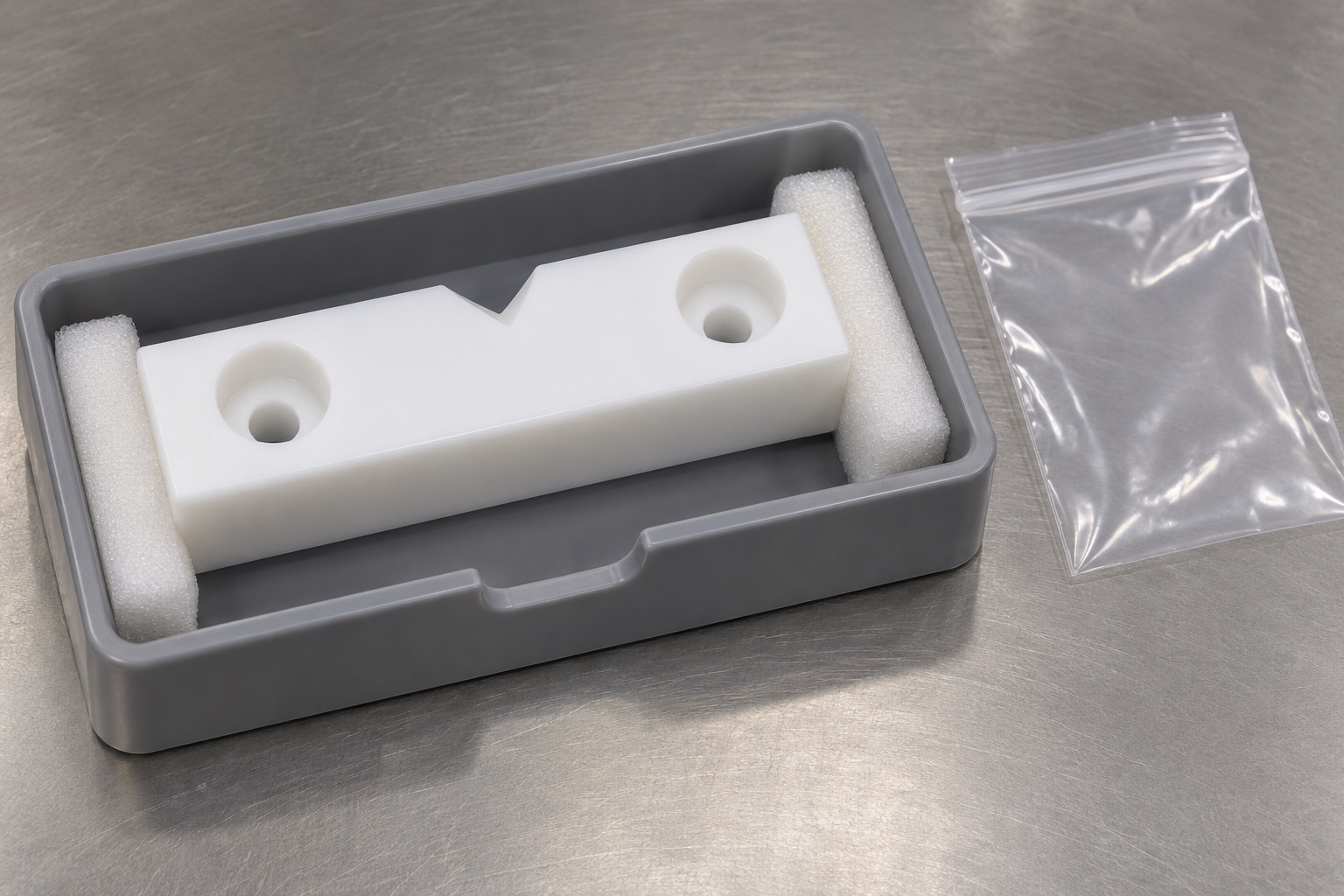
Protect the features that determine position
Package the fixture so the V faces and axial stop are not bearing shipping loads. A fitted insert can support an outer shoulder and provide separation from loose hardware. Locate the part identifier where the recipient can read it without placing a label on a contact flank. At receipt, check both the insert and the part for damage before trusting the previous inspection report. The appropriate protection depends on transport and handling conditions; no sterile barrier or storage life is implied.
Define what purchasing should request
Send a controlled drawing with the fixture and master interface, material grade, approved support condition, and known clearance restrictions. Request separate evidence for material identity, free part geometry, and bench seating. Mark unresolved installed checks in the order rather than asking the machining supplier to approve clinical use. At handover, tie the inspection report to the part revision and packaged lot. A useful acceptance package lets the owner distinguish a conforming machined block from a complete, approved imaging setup.
Manufacturer background reference: www.flukebiomedical.com.
FAQ
Can a V locate a cylinder in every direction?
No. Its two flanks locate transverse seating for the specified cylinder, but axial and rotational location need separate consideration. The actual constraints depend on the complete support and stop layout.
Does acetal make a fixture suitable for scanning?
Not by itself. The device owner must review the exact material, location, fasteners and intended scanning configuration. Material identity and mechanical geometry do not establish artifact or imaging performance.
Should the groove root support the cylinder?
Not if the design specifies support on the two flanks. Check the master at the allowed diameters so a root radius, local burr or chip cannot become an unintended contact point.
How is repeatability different from measuring a part twice?
In a reseating study the fixture or master is removed and reinstalled between observations. Repeating readings with nothing moved mainly describes the measurement setup, not the variation introduced by installation.
What should be marked on the inspection report?
Include the revision, master identification, reference construction, part support and individual readings where agreed. Keep observations from a functional seating trial separate from results for specified drawing characteristics.
Is protective packaging a sterile delivery claim?
No. Separating hardware and protecting the contact faces can limit damage during handling. Sterility or controlled cleanliness would need their own specifications, evidence and acceptance criteria.

tanghangyun@oemach.com