
Robot joint housings combine bearing bores, reducer and motor interfaces, angled faces, cross holes, cable passages and lightweight cavities. When each face is machined in a separate setup, fixture and coordinate errors accumulate across the housing.
Five-axis machining can keep many related features in one work coordinate system and reduce those transfers. It does not automatically guarantee position accuracy, and it does not always mean every surface is completed in a literal single operation.
The process must begin with assembly datums, expose the required faces without weakening support, calibrate the rotary kinematics and inspect all features in the same functional coordinate system.
Controls for one-setup multi-face machining
| Control point | Risk | Process response |
|---|---|---|
| Assembly datum | Machine coordinates do not match functional assembly | Use reducer, bearing or mounting interfaces to establish the datum frame |
| Fixture access | Tool or spindle collision and weak support | Expose required faces while supporting the main load path |
| Rotary accuracy | Indexed face shifts from pivot or TCP error | Calibrate rotary axes, probe the blank and verify tool-center control |
| Thin walls | Cavity roughing releases stress or causes chatter | Use balanced staged removal and leave critical finishing stock |
| Inspection | Independent best fits hide cross-face error | Align CMM results to the assembly datum and report related positions together |
Build The Coordinate System From Assembly Datums
The primary datum should represent how the housing locates in the joint: often a reducer face, bearing axis, mounting pilot or a defined combination. Secondary and tertiary datums establish clocking and axial position.
Multi-face hole patterns, motor interfaces and sensor features are then dimensioned from this common frame. If the machining zero and the inspection alignment use different logic, a part can pass one report and still misalign during assembly.
The released drawing should distinguish true functional position controls from general clearance features so process effort is concentrated where it affects the joint.
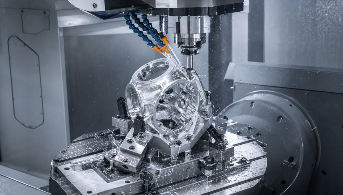
One controlled work offset can relate multi-face bores, hole patterns and mounting faces while reducing refixturing error.
Design A Fixture That Exposes Faces Without Losing Stiffness
A one-setup plan is useful only when the fixture allows safe spindle access and maintains support through roughing and finishing. The clamping interface may require a prior operation, meaning the complete route can still contain a preparation setup before the main five-axis cycle.
The fixture should avoid obstructing angled tools, probes and chip evacuation. It must resist changing cutting directions without deflecting the housing or crushing thin walls. Collision simulation should include the spindle body, holder, probe, clamps and the full rotary envelope.
Calibrate Rotary Axes And Verify The Work Offset
Five-axis positional performance depends on rotary-axis pivot calibration, tool-center-point control, probing accuracy, machine warm-up and thermal condition. Small angular errors become larger linear shifts as features move farther from the rotation center.
Probe accessible datums on the actual blank to establish or verify the work coordinate system. Tool length, runout and wear compensation should be controlled for critical bores. A verification artifact or in-process check can show whether indexed faces remain inside the allocated error budget.
Rough Deep Cavities Before Finishing Critical Interfaces
Joint housings often remove a high percentage of aluminum and leave ribs, bosses and thin walls. Finishing a bearing bore before aggressive cavity roughing allows later stress release and clamp movement to change the critical geometry.
Use balanced roughing from appropriate orientations, keep uniform stock around bearing, reducer and motor interfaces, and add a stabilization or rest step when material condition and wall geometry require it. Semi-finish the structure, then finish critical faces, pilots, bores and reamed or bored holes with stable tools and light loads.
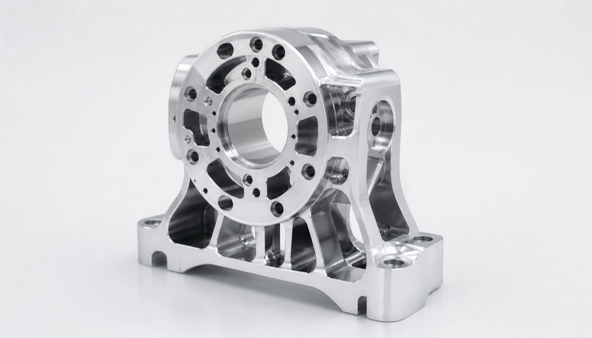
A single-setup strategy still requires rigid support, staged cavity machining, rotary calibration and protected finishing allowances.
Keep Multi-Face Features In One Controlled Chain
Angled holes, side patterns and cable passages can be indexed from the same probed origin. This reduces stack-up from separate fixtures and makes relationships easier to trace. Some very tight or deep bores may still need a dedicated finish process, but their datum transfer should remain explicit and verified.
Position tolerance is not only a machine readout. Feature size, form, burr condition, edge break and coating allowance may affect pins, fasteners and mating modules. Critical hole patterns should be finished and deburred without disturbing their locating edges.
Inspect All Faces In The Assembly Alignment
A CMM can align to the primary face, pilot or axis and evaluate multi-face positions, angular relationships, bores and hole patterns in one coordinate system. Independent best fits for each face can conceal the accumulated error the one-setup process was intended to control.
Inspection planning should define probing access, datum simulation, surface-treatment state, point distribution and whether threaded or slotted features require functional gauges. First-article results should be traceable to the same drawing revision and machine process used for repeat production.
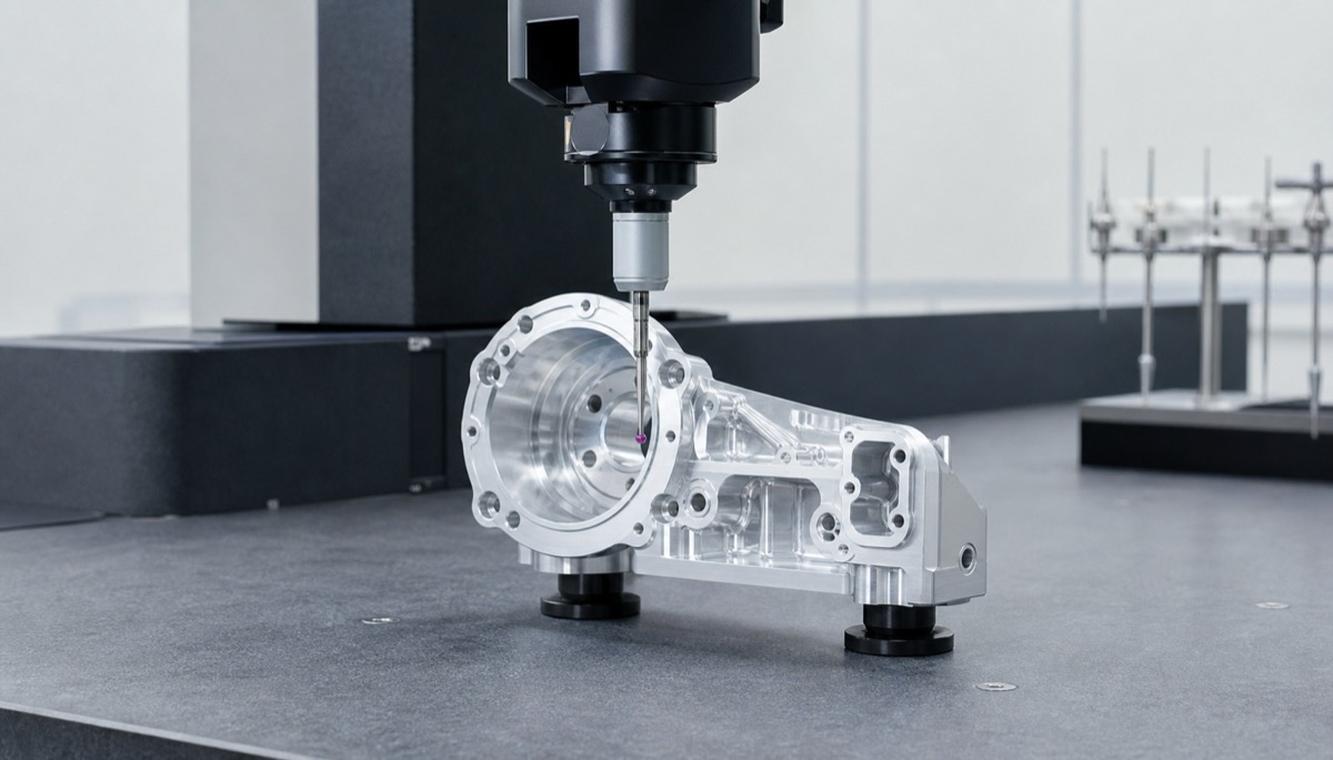
All critical features should be evaluated from the assembly datum system rather than independent face-by-face best fits.
Information To Include With The RFQ
A supplier can evaluate whether one-setup five-axis machining is justified only with the assembly and acceptance context.
- 2D drawing and 3D model with matching revision
- Primary assembly face, axis, pilot and clocking references
- Critical multi-face position and angular tolerances
- Bearing, reducer, motor, seal, sensor and cable interfaces
- Material condition, wall thickness, stress-relief needs and coating allowances
- Required CMM report, functional gauges, first-article quantity and repeat lot size
Summary
One-setup five-axis machining reduces refixturing error by relating multi-face features to one controlled coordinate system. The result still depends on functional datums, accessible and rigid fixturing, rotary calibration, staged material removal, protected finishing allowances and assembly-aligned inspection.
FAQ
Does one setup mean the housing needs only one operation?
Not always. A preparation operation may create the clamping interface, while one main five-axis setup controls the related functional faces and holes.
Does a five-axis machine automatically meet multi-face position tolerance?
No. Rotary calibration, fixture deflection, probing, tool condition, temperature and process sequence all contribute to the result.
Why not best-fit each face during CMM inspection?
Independent best fits remove the common assembly relationship and can hide the cross-face error that affects motor, reducer, bearing or sensor alignment.
When is a second finishing setup acceptable?
It can be acceptable for inaccessible or specialized features if the functional datum is transferred with quantified repeatability and the final inspection evaluates the complete relationship.
Ready to get a quote for your CNC machined parts?
Submit your engineering drawings to qiancj@oemach.com. We support prototype sampling and small-batch production with strict tolerance control.