
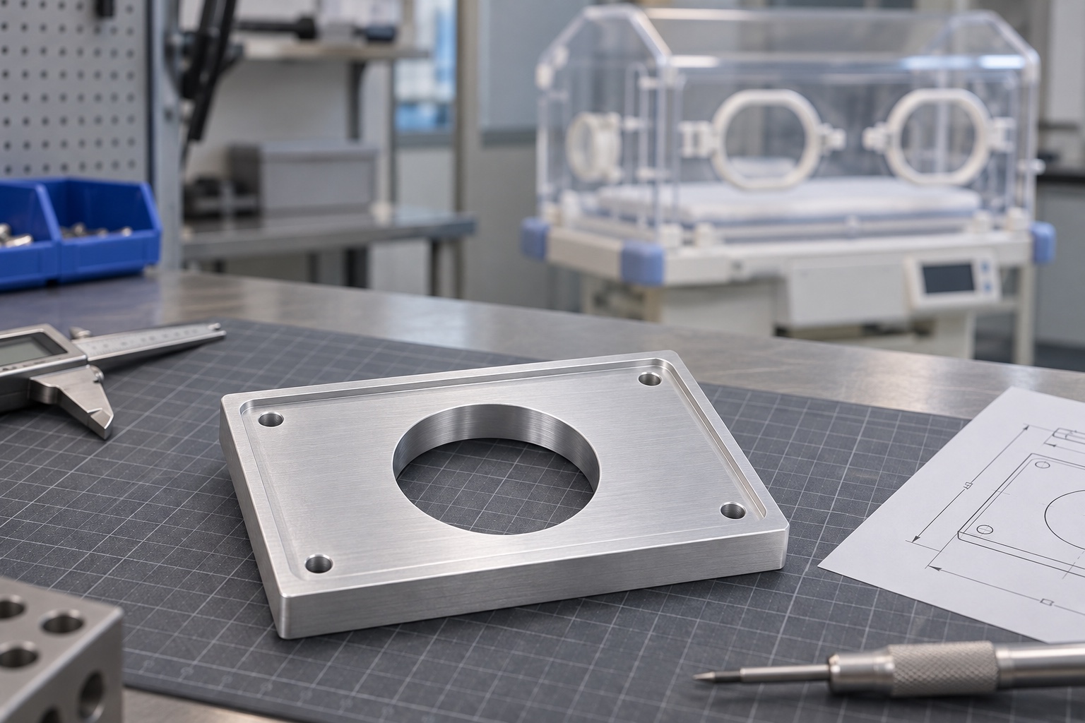
Define the plate as a mechanical interface
An incubator can use sensors to monitor environmental conditions. The geometry of a mounting plate, however, answers only a mechanical question: can a defined housing or surrogate sit at the intended position without an unintended contact? It does not establish what the sensor measures or how the complete equipment behaves. The plate discussed here is a bench development tool, not a field modification or spare part. Before detailing an opening, obtain the controlled envelope for the sensor and the receiving frame, and identify what must not touch the plate.

Separate the opening from the locating features
A circular opening can pass a cylindrical housing without locating it. If the housing is positioned by a flange, pins or a separate bracket, making the opening tight may create a second and conflicting location. Mark which surfaces carry the housing and which provide clearance. Account for connectors, molded shoulders and the path taken by the assembly before reaching its final position. A cross section through the interface can show where a housing that fits the nominal aperture would still be blocked by a step, chamfer or fastener head.
Define the usable mounting plane
An inspection report should state whether the base of the plate, the perimeter step or a set of mounting pads represents the primary plane. That choice determines how to interpret height and parallelism. Do not pull a thin plate flat with fasteners and present the readings as free-state dimensions. If the installed condition matters, define the bench frame, fasteners and seating conditions. Use both conditions where they answer different questions: one can show machining distortion, while the other shows the geometry seen by the intended assembly in the documented setup.
Make the hole pattern independently checkable
The four corner holes may retain the plate without precisely locating it. If a design uses a distinct side reference, name it and locate the opening and hole pattern relative to it. Drawings should distinguish plain clearance holes from any feature intended to position a fastener or pin. Discuss access to both faces, since a projecting screw or an exit burr can change the result. If a pattern fits a bench frame only when the plate is pushed sideways, record that condition rather than reporting that the hole positions were measured and accepted.
Allocate clearance across more than one part
List the variation from plate thickness, opening position, surrogate diameter, frame position and any finishing layer. Clearance at the entry does not necessarily represent clearance through the full opening. Include the connector and cable envelope where the bench check requires it, but do not specify routing for a real device from a drawing of the test plate. For a first prototype, ask which part of the stack is fixed and which part remains adjustable. Leave undecided ranges explicit instead of covering them with an arbitrary oversized opening.
Choose the material and surface condition together
Aluminum can make a trial plate easier to handle, but the exact alloy, temper and stock condition should be agreed with the owner. If a coating or surface treatment is planned, define whether the opening and step are inspected in their finished condition or protected from the treatment. Material identity does not establish corrosion behavior in a humid enclosure. No result from the bench fixture should be used to claim environmental suitability, cleaning compatibility, thermal response or performance of a sensor in an incubator. These are separate validation topics for the equipment owner.
Preserve plate geometry while removing stock
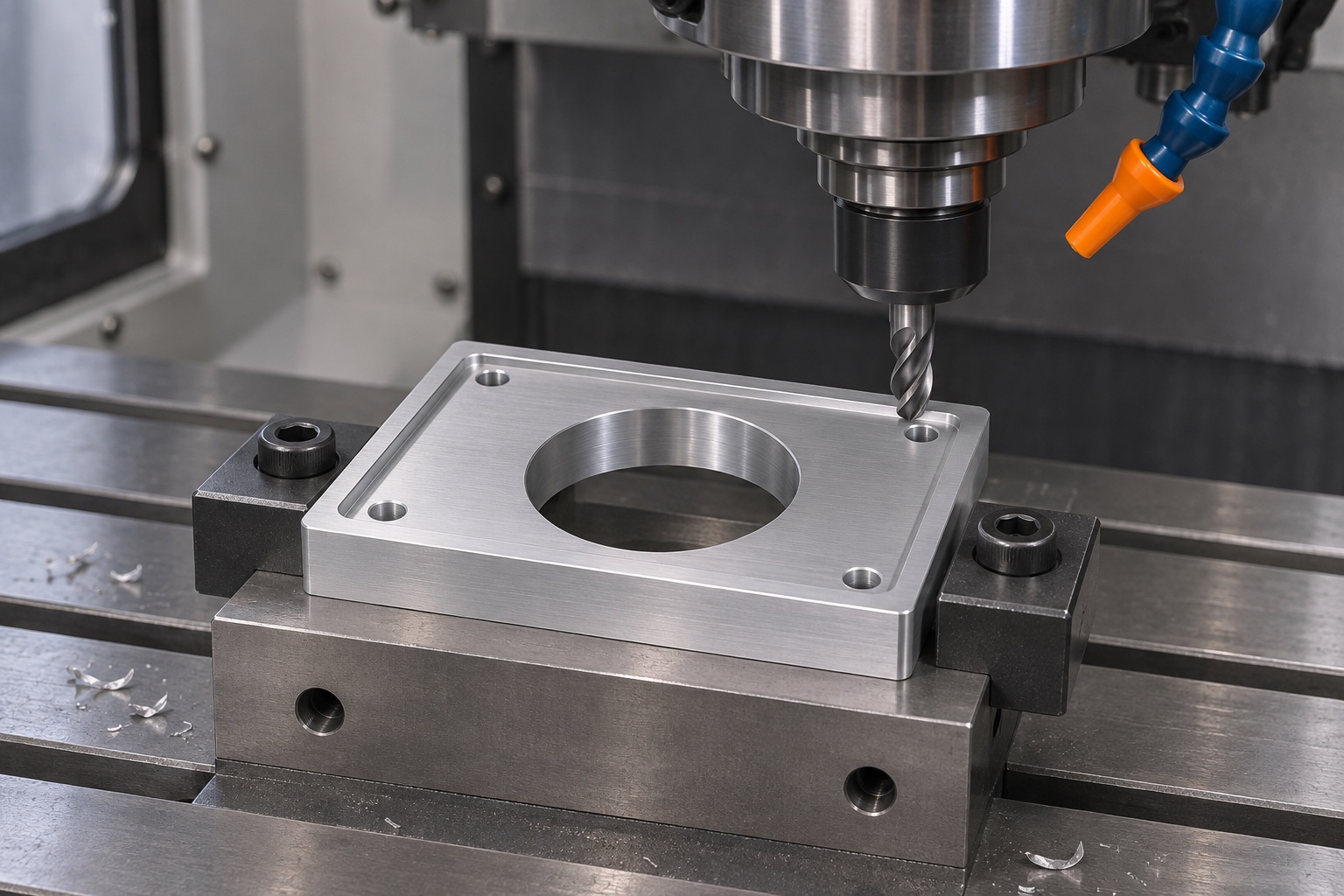
Support the blank near machining loads and avoid pulling a warped blank flat against a fixture. A candidate sequence faces stable references, roughs the aperture and perimeter step, then checks the released plate before finishing. Consider what happens as the center opens and the remaining flange becomes less stiff. Locate the mounting holes from the reference system that the inspection team can reproduce. If the plate is moved between setups, document the transfer features and inspect the characteristics most likely to shift. The illustrated tool position is not a cutting instruction.
Inspect the step and aperture with different methods
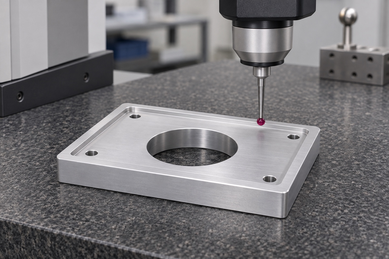
An appropriate measurement plan can record step heights at several named stations, and aperture size, form and position in the zone that actually passes the surrogate. A single diameter taken on the entry edge can include a chamfer or miss a local restriction. Identify probe access and the support condition before assigning methods. The four holes can be checked for size and relation to the stated references, independently of a fit trial. Label stations on a sketch so an inspector at receipt can repeat the check without guessing where a reading was taken.
Plan a dry trial with a controlled surrogate
A useful trial can use a rigid, identified dummy housing without connecting electronics or energizing a medical device. Record orientation, entry path, contact at the flange and any clearance around the cable envelope. Repeat from an independent removal and insertion if the purpose is to examine seating consistency. If the surrogate sticks, first check its revision and check for debris or a raised edge. Do not widen the aperture before the cause is known. The dry trial does not measure humidity, temperature, airflow or sensor response.
Keep edge corrections visible in the record
A burr on a corner hole, a high mark on the step and an impact near the opening can affect different checks. Agree on edge conditions and allowable rework before inspection. Avoid blending a reference surface after measurement simply to improve a one-off fit. If work is authorized, recheck any affected dimensions and mark the measurement record accordingly. Cleaning loose machining debris is a handling operation; it is not evidence of disinfection or approved cleaning in an incubator. Keep any labels away from the step and other functional contact surfaces.
Protect the plane from damage in transit
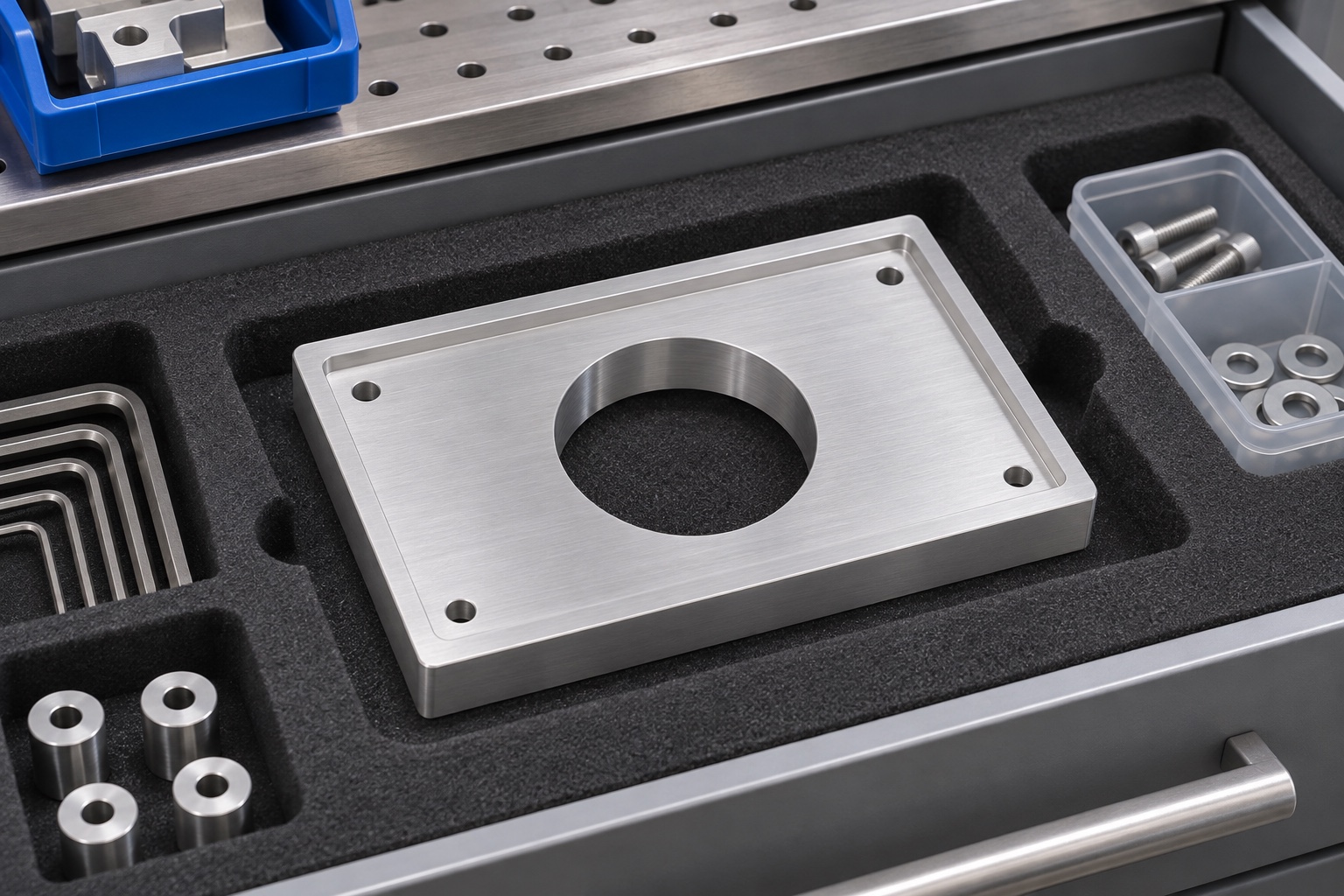
Use a protective insert that supports the plate on suitable exterior regions without bearing on the step or deforming a thin edge. Separate loose hardware and use the package to identify the revision and lot. At receipt, examine the insert for compression and the plate for raised marks before repeating a fit check. Any package that claims a defined clean or sterile condition requires separate requirements and evidence. The illustrated protection is intended only for transport and storage of a bench item, not for clinical use or a stated service life.
Give the receiving team a reproducible package
Supply the plate drawing, reference housing envelope, material specification, inspection condition and a sketch of the seating trial. Request separate records for material identity, measured geometry and bench observations. Identify unresolved interfaces explicitly, especially if a real sensor or incubator is not available for review. An acceptable part may still leave unresolved cable, environmental or device questions. The goal is a reproducible fit check that can be repeated by a second team without confusing it with approval of the complete incubator or instructions for service in a patient environment.
Manufacturer background reference: www.draeger.com.
FAQ
Does the opening locate the sensor?
Only if the controlled design assigns it that function. An aperture can provide clearance while a different face or feature sets the mechanical location.
Which condition should the plate be measured in?
Follow the drawing. A free-state check reveals plate geometry without fastening, while a mounted check can describe the relation to the approved bench frame.
Can a larger opening cure an insertion problem?
Not without identifying the cause. Interference may be at a step, burr, cable envelope or wrong reference, rather than at the functional diameter.
Does a dry fit test the incubator?
No. It checks mechanical contact and clearance in the specified setup. It says nothing about environmental control, device safety or sensor accuracy.
Can the illustration be used as an installation drawing?
No. It shows a generic concept. Any real equipment installation requires the equipment owner's approved drawing and procedures.
Is the example packaging sterile?
No. It protects the plate from handling damage. Cleanliness and sterility claims require separate defined controls and validation.

tanghangyun@oemach.com