
The best bore-finishing method is not determined by diameter tolerance alone. A bearing seat may need size, roundness and axis control; a dowel hole may prioritize position and repeatability; a nonstandard pocket may need contour flexibility.
Finish milling, fine boring and reaming overlap in achievable size ranges, but they do not correct the same errors. Machine condition, tool overhang, material, bore depth, wall stiffness, setup and temperature can move the result outside any published capability table.
The ranges below are planning references for stable setups, not unconditional limits or acceptance promises. Final feasibility must be reviewed against the released drawing and inspection method.
Typical planning comparison for bore-finishing methods
| Method | Typical planning capability | Best use and main limitation |
|---|---|---|
| Finish circular milling | Often IT8-IT10; roughly ±0.02 to ±0.05 mm size control and Ra 1.6-3.2 µm in stable work | Flexible for nonstandard diameters and position adjustment; circularity and finish depend strongly on interpolation, runout and tool deflection |
| Fine boring | Often IT6-IT8; roughly ±0.005 to ±0.015 mm and Ra 0.8-1.6 µm with a stable short tool | Strong control of diameter, roundness and axis; requires access, rigid setup and tool adjustment |
| Reaming | Often IT6-IT8; roughly ±0.005 to ±0.015 mm and Ra 0.4-1.6 µm with a correct pre-hole | Efficient for standard repetitive holes; follows the prepared hole and has limited ability to correct position or axis error |
| Deep or high aspect-ratio bore | Capability must be reviewed separately | Chip evacuation, guidance, thermal growth and straightness may require gun drilling, line boring, honing or grinding |
Define Accuracy As More Than Diameter
Bore acceptance can include local size, roundness, cylindricity, straightness, surface texture, position, perpendicularity and coaxiality. These characteristics are related but not interchangeable.
A two-point bore gauge may confirm diameter while missing lobing or axis error. The drawing should identify the functional datum, fit, controlled depth and whether coating or heat treatment occurs before final acceptance.
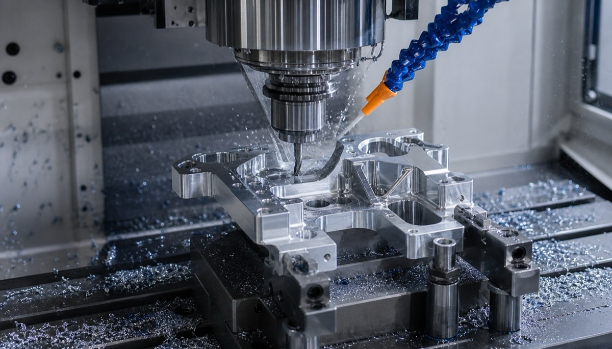
Finish milling, fine boring and reaming use different cutting mechanics; the process should be selected from size, form, location, depth, material and batch requirements.
When Finish Milling Is The Practical Choice
Circular interpolation with an end mill is flexible for prototypes, nonstandard diameters, interrupted bores and features that need position adjustment from a common work offset. One tool can cover several diameters and leave stock for a later process.
Its result is sensitive to spindle runout, tool deflection, interpolation accuracy, entry strategy and cutting direction. It is usually a practical semi-finish or moderate-tolerance finish method, but demanding bearing fits often need boring, reaming, honing or grinding afterward.
When Fine Boring Provides Better Geometric Control
A fine boring tool cuts the final diameter with an adjustable, controlled cutting edge. In a rigid setup it can improve size, roundness and axis definition, making it a common choice for bearing seats and larger precision bores.
Boring can correct a modest pre-hole offset better than reaming, but it cannot rescue an unstable wall or an incorrect datum chain. Tool overhang, balance, insert condition, stock uniformity and spindle thermal state still govern the result.
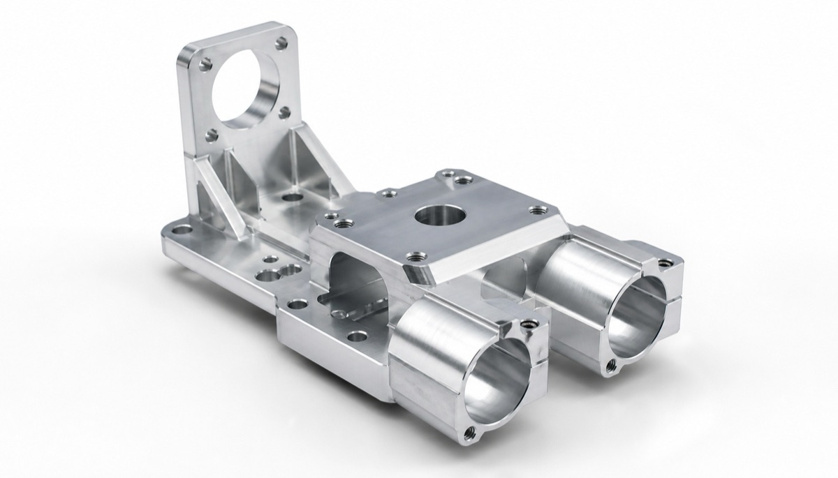
Different holes on the same part can justify different finishing methods instead of one tolerance and one process for every feature.
When Reaming Is Efficient And Repeatable
Reaming removes a small, consistent allowance from a prepared hole. It can provide repeatable standard sizes and a good surface in production when pre-hole diameter, straightness, allowance, alignment, lubricant and chip control are stable.
A reamer tends to follow the existing hole. It should not be selected as the primary correction for poor position, angular error or severe runout. Blind holes, cross holes, tough materials and interrupted cuts require specific tool geometry and process validation.
Build The Process Around Location And Datum Control
Critical holes should be roughed and semi-finished before the structure is weakened, then finished after the functional datum becomes stable. Related bores may need one setup or a qualified datum transfer to preserve position and coaxiality.
Do not assign the tightest bore tolerance to every clearance feature. Separate bearing fits, dowel holes, seal bores and general relief holes, and match each to the lowest-risk process that satisfies its actual function.
Inspect With The Method Used For Acceptance
Plug gauges and bore gauges are efficient for size; roundness equipment reveals form; a CMM evaluates position and axis relationships from the datum reference frame. Surface texture may need a profilometer rather than visual inspection.
Agree on measurement depth, point distribution, free or clamped state, temperature and reporting format before quotation. A supplier capability statement is useful only when it matches the same characteristic and inspection definition.
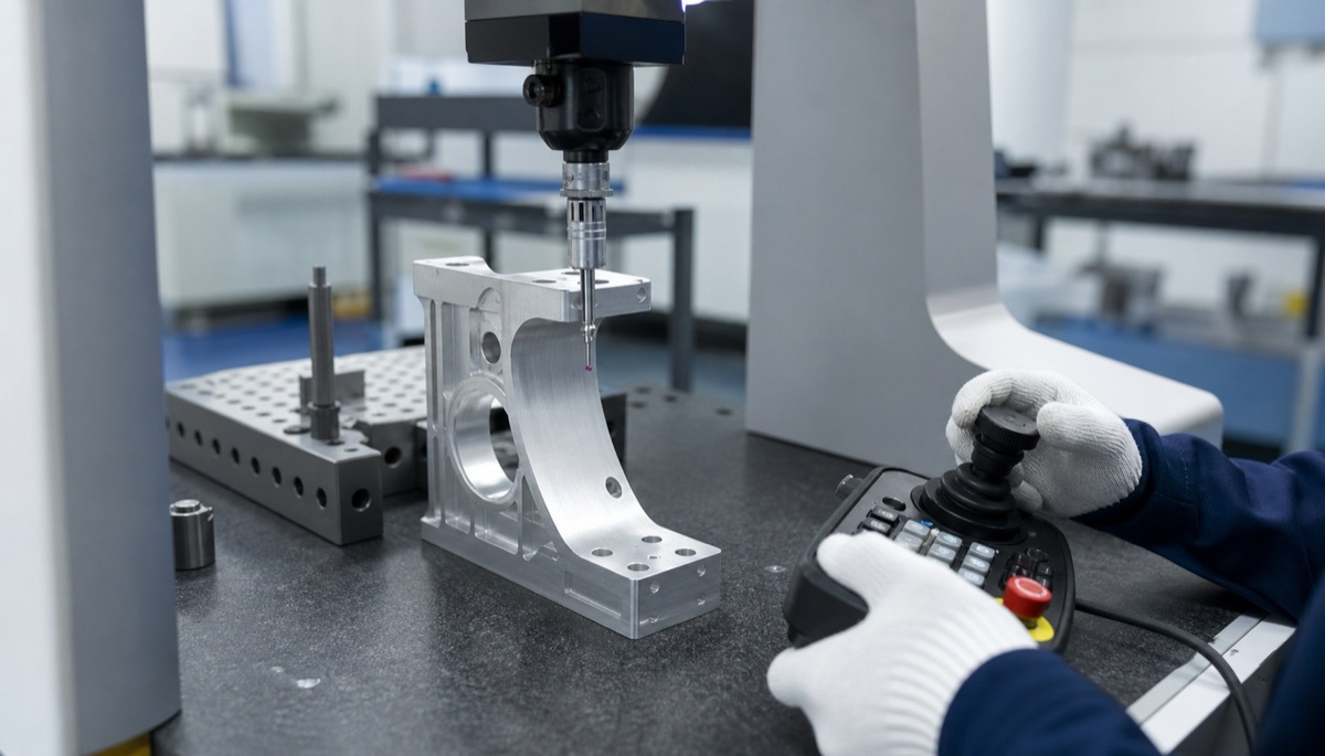
A diameter result alone does not prove position, axis orientation, roundness or coaxiality to the assembly datum.
Information To Send With The RFQ
A complete RFQ lets the supplier select the finishing route and inspection plan without adding hidden assumptions.
- 2D drawing and 3D model with matching revision
- Bore diameter, tolerance, depth, aspect ratio and interrupted features
- Required fit, surface texture, roundness, cylindricity, position and datum references
- Material, condition, heat treatment, coating and final acceptance stage
- Prototype and repeat quantity, interchangeability and process-capability expectations
- Gauge, CMM, roundness or surface-finish report requirements
Summary
Finish milling offers flexibility and position adjustment, fine boring offers strong diameter and axis control, and reaming offers efficient repeatability when the pre-hole is already correct. Select the method from the complete functional requirement, then validate it with the same datum and measurement definition used for acceptance.
FAQ
Can reaming guarantee hole position?
Not by itself. Reaming mainly improves size and surface and usually follows the prepared hole, so position depends on the upstream datum and pre-hole process.
Is fine boring always more accurate than finish milling?
It often has an advantage for diameter, roundness and axis control, but a weak setup, long tool or unstable wall can remove that advantage.
Can one tolerance range be used for every bore diameter?
No. Diameter, depth, aspect ratio, material and access affect capability, so each critical feature needs a specific review.
Which inspection method is best for a bearing bore?
Use a bore gauge for size, form equipment when roundness or cylindricity is critical, and CMM inspection for position and axis relationships to assembly datums.
Ready to get a quote for your CNC machined parts?
Submit your engineering drawings to qiancj@oemach.com. We support prototype sampling and small-batch production with strict tolerance control.