
A distorted CNC part is not solved reliably by simply reducing feed or increasing clamp force. The correction depends on whether the part moves during cutting, springs back after unclamping, or drifts after resting.
Residual stress changes the internal force balance as material is removed. Clamping force can hold a flexible part in an artificial shape. Cutting heat creates temporary dimensional gradients and can compound both effects.
A useful investigation records the part at defined process states and separates these mechanisms before changing the route.
How to distinguish the three main deformation causes
| Observed behavior | Likely cause | First process response |
|---|---|---|
| Part changes after roughing or continues moving after rest | Residual stress or unstable material condition | Use balanced stock removal, rough/semi-finish stages and stabilization before final cuts |
| Part measures correctly while clamped but springs back after release | Clamping force and inadequate support | Reduce and distribute clamp load, improve support and inspect in the free state |
| Dimensions drift with cycle time or differ hot versus cold | Cutting and environmental heat | Stabilize toolpath and coolant, control cycle heat and measure at defined temperature |
| Several behaviors occur together | Combined stress, clamping and thermal effects | Run controlled checks at each state rather than changing multiple variables at once |
Residual Stress Appears When The Force Balance Changes
Rolled plate, extrusion, forging, casting, heat treatment and prior straightening can leave internal stress. Removing a large pocket or machining one side first changes the balance and allows the remaining structure to move.
Use material with an appropriate condition, verify stock direction where relevant, remove material symmetrically and separate roughing from finishing. A rest, thermal stabilization or stress-relief step may be justified by material, wall geometry and tolerance, but it should be planned rather than added blindly.
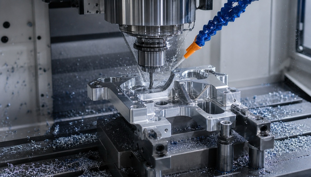
Balanced stock removal, local support and controlled cutting heat address different deformation mechanisms and should not be treated as one generic fix.
Clamping Can Create A False Geometry
A thin wall or broad plate can be pulled flat against a fixture and measure correctly during machining. Once released, it returns toward its natural shape and the finished surface appears warped.
Place supports near the cutting load path, use the minimum repeatable clamp force and avoid unsupported spans. Soft jaws, vacuum fixtures, low-pressure clamps or conformal supports can help, but each must be checked for contact, leakage, local imprint and repeatability.
Cutting Heat Produces Temporary And Uneven Growth
A hot tool, concentrated toolpath or unstable coolant flow can create local expansion. Finishing one area immediately after heavy roughing can lock the process to a transient thermal state.
Use sharp tools, stable engagement, balanced path sequencing and adequate coolant or air strategy for the material. Allow the machine and part to reach a controlled condition before critical finishing and do not compare hot shop-floor readings directly with stabilized metrology results.
Use A Staged Route For Thin Walls And Deep Cavities
Rough the main volume while leaving uniform stock around critical faces, bores and rails. Re-establish datums after relaxation, semi-finish the structure, then finish the functional interfaces with light, balanced cuts.
Five-axis access can reduce refixturing, but it does not remove material stress or clamp distortion. The fixture and sequence still need to preserve stiffness as the part becomes thinner.
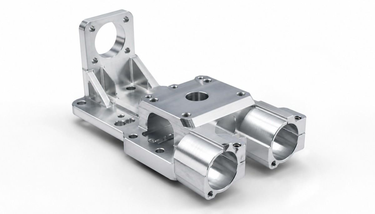
Large stock removal and uneven wall sections require staged roughing and protected finishing allowance around functional interfaces.
Measure At Defined States To Find The Cause
Record dimensions while clamped when useful, immediately after release, after a defined rest and at the specified inspection temperature. A change at release points toward clamping; delayed movement points toward material stress; temperature-correlated drift points toward heat.
CMM alignment should follow the drawing datum and measurement condition. Best-fitting a warped surface can hide the functional error. Flatness, profile, bore location and mounting relationships should be reported in the state used for acceptance.
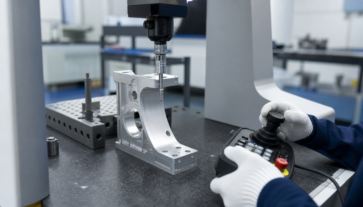
Measurements immediately after cutting, after unclamping and after stabilization help separate thermal drift, clamp springback and residual-stress movement.
Information To Send With The RFQ
Deformation risk can be priced and planned only when the stock and acceptance state are known.
- 2D drawing and 3D model with critical datums and free-state requirements
- Material grade, temper or heat condition, stock form and grain or extrusion direction
- Raw-stock size, material-removal ratio, wall thickness and deep-cavity regions
- Mating conditions, assembly preload and surfaces that may be restrained in service
- Surface treatment, heat treatment and whether dimensions apply before or after them
- First-article measurements, rest time, inspection temperature and repeat-batch sampling
Summary
Diagnose deformation by when and how the part moves. Residual stress needs balanced staged material removal and stabilization; clamping distortion needs better support and lower distributed force; cutting heat needs controlled engagement, cooling and measurement temperature. The final acceptance state must be defined before machining begins.
FAQ
Will more clamp force prevent deformation?
It may suppress movement during cutting but can increase springback after release. Improve support and use the minimum repeatable force instead.
Does thicker raw stock guarantee a stable part?
No. Material condition, stock direction and the amount and order of removal can still release significant residual stress.
How can thermal distortion be distinguished from residual stress?
Thermal movement correlates with part temperature and cycle timing and often reduces after stabilization; residual-stress movement can remain or continue after the part is cold.
Should a thin-wall part be inspected clamped or free?
Follow the drawing and assembly function. If acceptance is free state, report it free; if service restraint is functional, define the restraint method explicitly rather than assuming it.
Ready to get a quote for your CNC machined parts?
Submit your engineering drawings to qiancj@oemach.com. We support prototype sampling and small-batch production with strict tolerance control.