
A curved robot housing has functional mounting areas, sealing features and visible surfaces with different acceptance needs. Treating every surface with one toolpath or one roughness value can waste time and still leave visible defects.
The process should classify surfaces first, then align fixturing, toolpath continuity, cutting tools and inspection with each function.
Surface risks and controls
| Risk | Cause | Control |
|---|---|---|
| Visible blend line | Setup, tool or overlap mismatch | Place blends deliberately and keep datum/tool data consistent |
| Local undercut or overcut | Axis motion, deflection or stock variation | Simulate, use stable tools and verify form |
| Dimension changes after finishing | Blasting, anodizing or coating | Define masking, allowance and post-process checks |
Classify functional and visible surfaces
Mark mounting, sealing, bearing and cosmetic regions on the drawing or process model. Functional geometry takes priority, while visible regions need consistent texture and controlled transition zones.
Design the fixture for access and rigidity
Clamp away from cosmetic areas when possible and support the housing near cutting loads. Plan unavoidable flips so their blend zones occur in low-risk locations and use transferable datums.
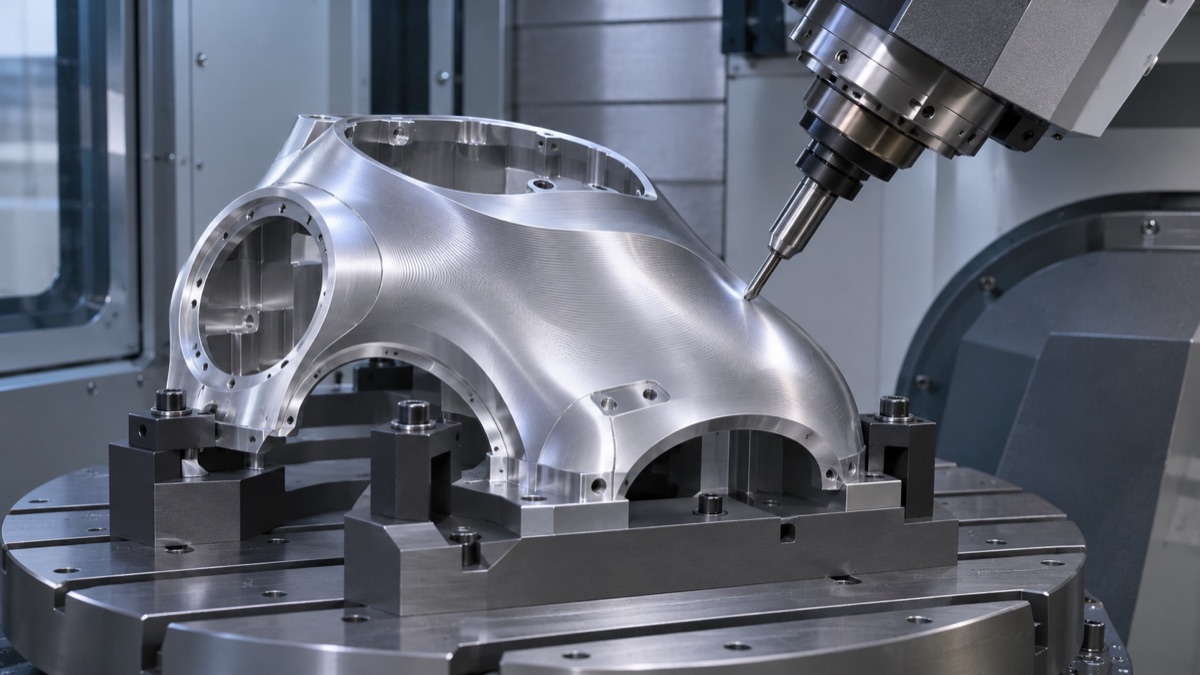
Tool-axis continuity, stepover and stable support influence both form and visible texture.
Smooth the tool-axis and path
Abrupt axis changes, uneven stepover and inconsistent entry or exit can create bands. Use a suitable ball or bull-nose tool, minimum practical overhang and verified path smoothing.
Keep finish stock uniform
Roughing should leave predictable stock on the curved surface. Uneven stock changes cutting force and deflection, which can appear as both form error and optical variation.
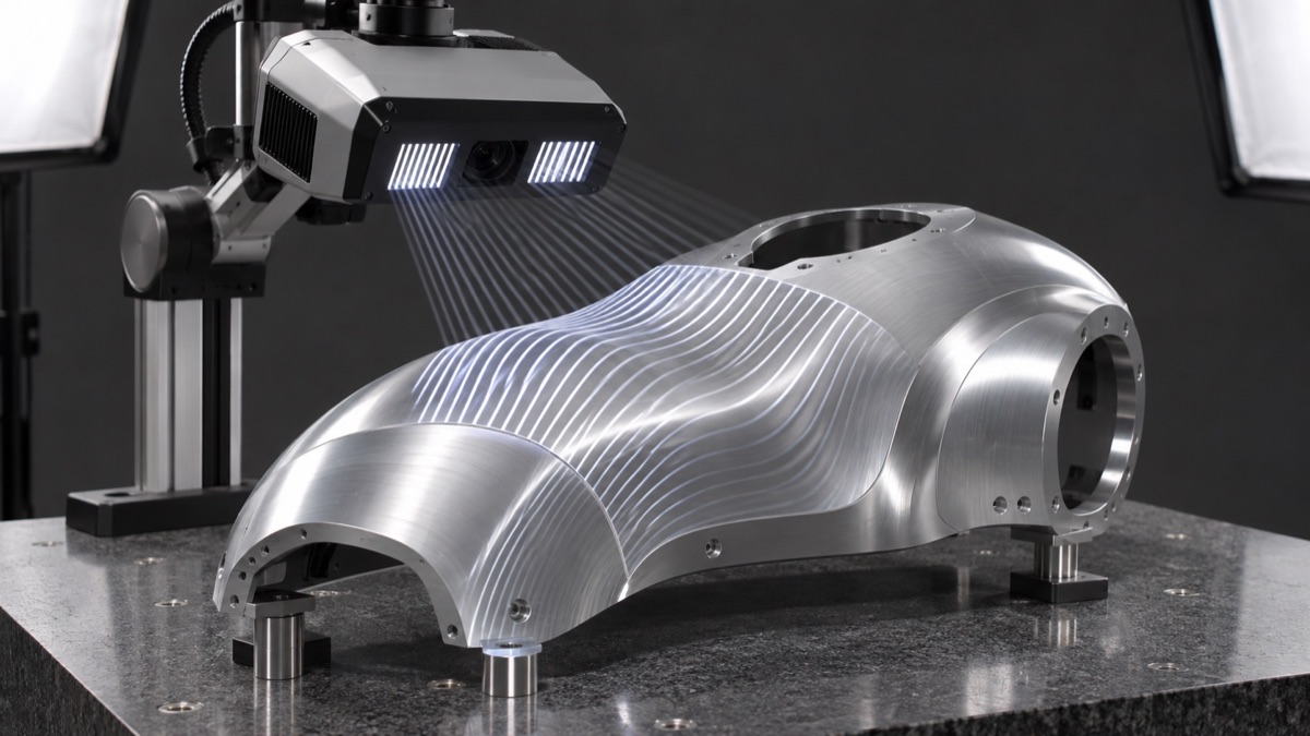
Scanning and controlled lighting reveal form deviation, blend lines and inconsistent reflection.
Inspect form and appearance separately
CMM scanning, structured light or profiles can verify form; controlled lighting and reflection checks reveal visible inconsistencies. Reinspect critical features after blasting, anodizing or coating.
Summary
Good five-axis housing surfaces come from early surface classification, rigid accessible fixturing, smooth tool-axis motion, uniform stock and separate dimensional and visual acceptance methods.
FAQ
Does five-axis machining eliminate blend marks?
No. It can reduce setups, but path transitions, tool condition and stock still create marks.
Why can Ra pass while the surface looks uneven?
A local Ra value may not capture waviness, path bands, reflection changes or blend lines.
Will blasting hide every machining mark?
No. It may reduce contrast but can also reveal inconsistent preparation and alter edges or dimensions.
Ready to get a quote for your CNC machined parts?
Submit your engineering drawings to qiancj@oemach.com. We support prototype sampling and small-batch production with strict tolerance control.