
Define the manufacturing question
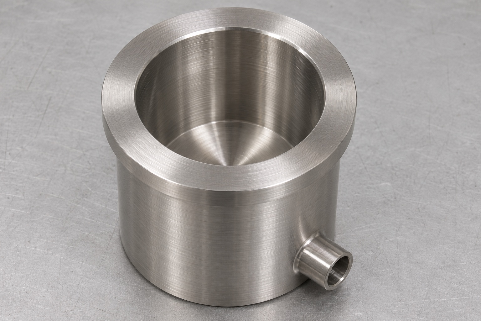
316L CNC turning for an analyzer probe wash cup starts with geometry, not a promise about cleaning performance. The cup has a central cavity, a top reference rim and a drain connection whose internal intersection needs controlled finishing. A supplier can manufacture and measure these features against an approved drawing. That evidence alone cannot establish probe cleanliness, carryover, reagent compatibility or analyzer accuracy. This guide considers the machining and inspection of a generic cup, without claiming a released device design or compatibility with a named analyzer. Application validation remains separate from the dimensional acceptance of the component.

Relate the cavity to the installed probe path
Identify the mounting reference that positions the cup in the equipment. Then define the cavity axis and the rim height relative to that reference. A bore of the correct diameter can still be incorrectly positioned beneath the probe. Avoid describing the relation only as a cosmetic concentric ring on the top face. If the mounting interface is cylindrical, specify its axis and locating shoulder; if it uses a flange, identify the seating face and clocking feature. Review the probe envelope separately from any clearance chosen for fabrication, because the supplier should not infer the motion of the installed instrument.
Specify 316L stock and the final condition
Specify the material designation, stock form and any required material documentation before machining. Do not substitute another stainless grade simply because its appearance is similar. List subsequent surface treatment and cleaning requirements separately from the alloy name. A drawing that requires a finished bore after treatment should make that timing clear. If a supplier proposes an alternate stock size or process route, review the change before production. The purchase specification should also distinguish ordinary machining cleanliness from a separately defined analytical cleanliness requirement; neither the material label nor a bright surface proves an application is ready for use.
Plan CNC turning around accessible reference surfaces
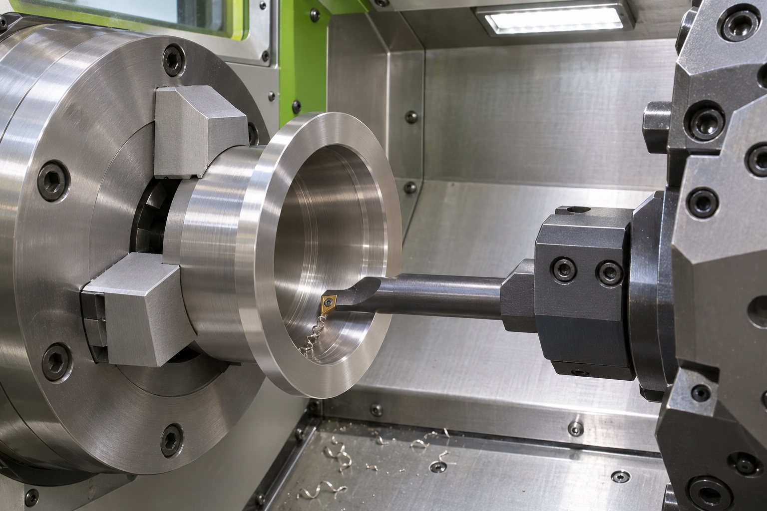
Face the stock and establish the turning reference before finishing the cavity and its locating features. Keep unsupported tool length and part projection appropriate to the actual geometry. Choose roughing and finishing passes that produce a stable cutting action instead of repeatedly rubbing the wall. Tool condition, chip evacuation and access to the cavity floor need review together. The purpose of a process plan is to preserve the drawing relationships through the machining sequence, not to assume a particular spindle speed fits every wash cup. Record which surfaces remain available for supporting the second operation without damaging the finished bore.
Locate the radial drain before cutting the intersection
The drain position depends on a clear height and angular reference. Show where it intersects the cavity and which portion of the connection carries the functional size. A hole drilled from outside can break through with material raised at the internal edge. The drill exiting into the cavity is therefore an intermediate process state, not automatically a finished feature. Consider access for inspection and approved edge finishing while reviewing the design. If the drawing requires a separate fitting rather than an integral connection, define that interface explicitly; do not treat the two constructions as equivalent without approval.
Make internal edge requirements inspectable
Describe the allowed edge condition at the drain intersection so that the machinist and inspector evaluate the same feature. An unspecified instruction to remove every sharp edge may lead to excessive rounding or an altered outlet profile. Identify the location, permitted treatment and any nearby surface that must remain unchanged. Confirm that the proposed tool can reach the inside without scratching the opposite wall. A sample photograph can help locate the feature but should not replace a dimensional or finish requirement. After any correction, inspect the affected bore and drain again rather than accepting the earlier measurements as final.
Separate surface roughness from visual appearance
An attractive turned surface does not establish the specified roughness. If roughness is important, identify the surface, parameter, evaluation direction and an accessible measurement method. A small curved cavity may limit the measuring instrument that can be used. Resolve that limitation before ordering a finish the supplier cannot verify. Also distinguish waviness, tool marks, pits and local burrs; one number does not describe every defect. Claims about cleanability or residue removal require an application-specific assessment beyond the roughness record. Avoid adding a lower roughness value merely because it sounds more suitable for medical equipment.
Inspect bore, rim and drain as separate characteristics
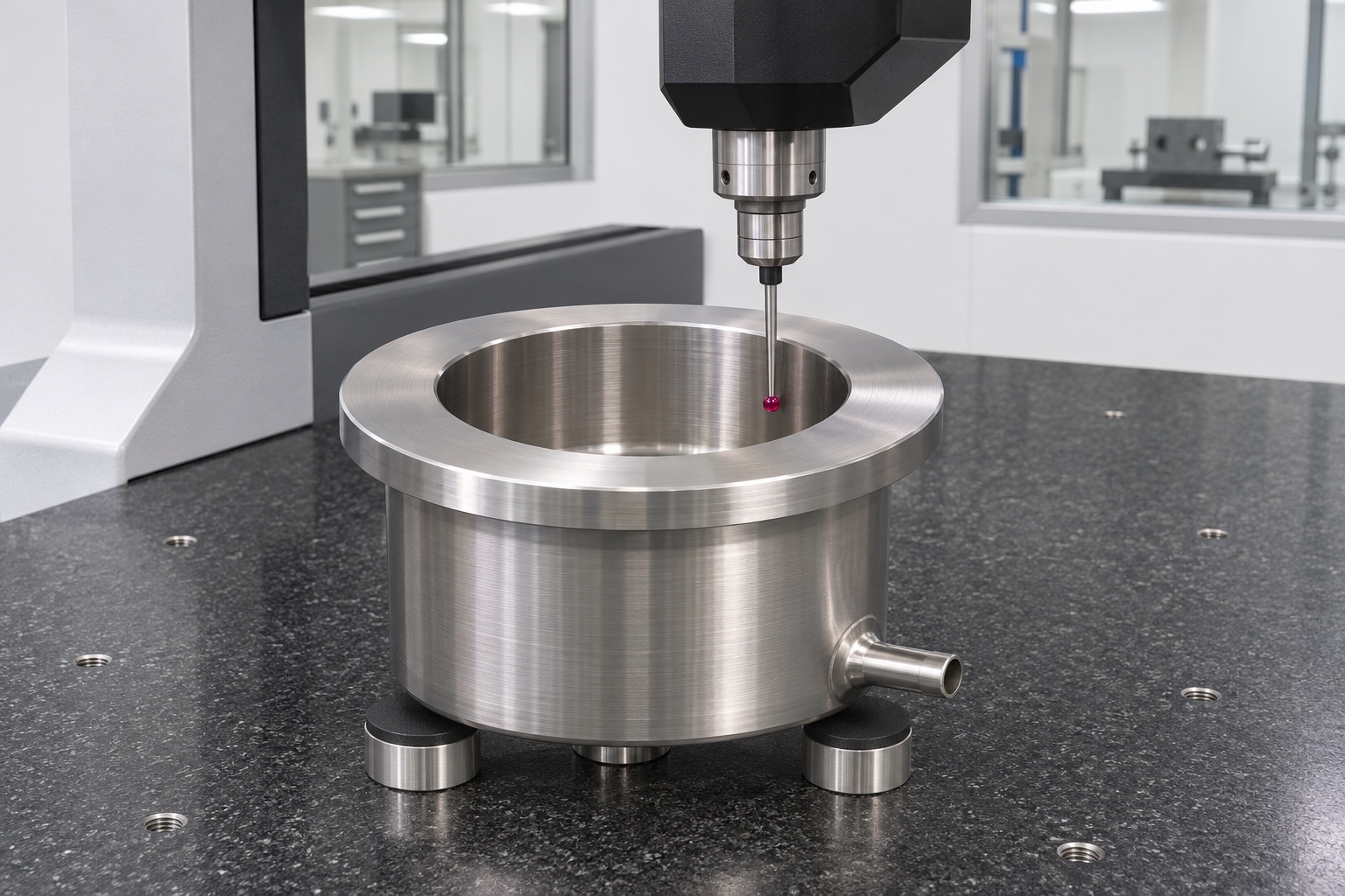
Measure the cavity at defined depths rather than only at the entry chamfer. Check the rim and locating surface in the same documented datum system. Inspect the drain size and location using a method suited to the access, and separately examine the internal breakthrough for raised material. A pin passing through the drain does not prove that the internal edge has been finished correctly. Coordinate measurement can help evaluate geometric relationships when probe access is adequate, but the inspection plan must identify what the stylus can actually reach. Record any feature requiring a different method instead of leaving it implicitly accepted.
Keep geometric tests separate from functional validation
A controlled dry assembly with an inert reference can reveal mechanical interference or an obstructed opening. It cannot establish the performance of a wash cycle. Fluid behavior, drainage under installed conditions, residue removal and chemical exposure require their own approved methods and acceptance criteria. Do not run an improvised trial on an operating analyzer to compensate for an incomplete component drawing. If a part appears to retain material, first identify whether the issue is geometric, surface-related or part of the wider system. A machining change should follow a reviewed requirement, not an undocumented adjustment made until the assembly seems to work.
Handle deviations without losing the reference
When a bore or drain is out of requirement, record its measured condition and the inspection setup before choosing a correction. Reworking the drain may change the intersection, remaining wall or connection geometry. Reworking the cavity can alter its relationship to the mounting reference. Obtain approval for changes that affect the design and identify which characteristics must be rechecked. Do not polish away the evidence of a defect before understanding its location. A useful disposition distinguishes a measurement error, a removable burr and an incorrect machined feature; these require different actions even if they all first appear as an assembly obstruction.
Protect the cup during ordinary transport
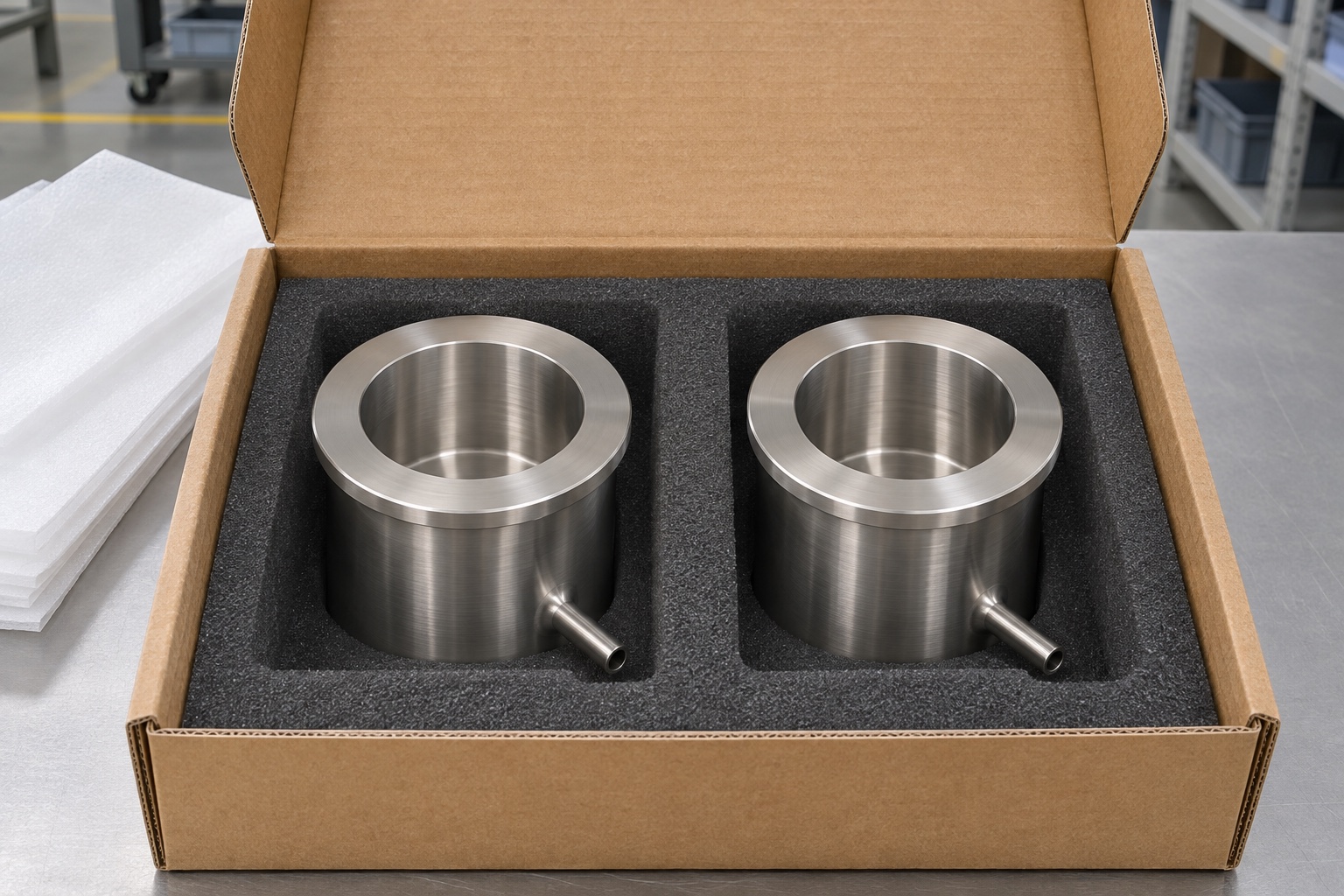
Separate components so that rims, bores and drain connections do not strike adjacent parts. Support the cup at robust exterior surfaces and provide clearance around any projecting connection. Define whether protective inserts, bags or closures are permitted and ensure they do not leave unacceptable residue. Ordinary packaging protects geometry during handling; it is not evidence of a sterile condition or a validated cleanliness level. Keep identification associated with the package rather than marking an uncontrolled area of the component. If the receiving team must repeat dimensional inspection, make it possible to remove the part without loading its delicate features.
Prepare a useful machining request
A request for a stainless analyzer wash cup should include the controlled drawing, material specification, quantity, critical geometric relationships, edge requirements and the required finish condition. Add the inspection deliverables and packaging constraints that are actually needed. State which requirements are design inputs and which are still awaiting engineering review. For a new part, agree how first-article findings will be handled before committing to a larger batch. This lets a supplier price the machining and verification work without inventing a device specification. A clear request is more useful than a generic instruction to make a medical-grade cup with an exceptionally smooth bore.
FAQ
What is the main datum for wash cup machining?
Use the drawing's actual locating interface and its related seating face. The cavity axis and drain location must be related to those references, not inferred from appearance.
Does 316L automatically prove cleaning compatibility?
No. Alloy identity and machining records do not establish compatibility with the intended chemicals, exposure conditions or validated cleaning process.
Why inspect the drain breakthrough separately?
An externally correct hole can still have a raised internal edge. Hole size, location and breakthrough condition are distinct checks.
Can a plug gauge verify the whole cavity?
No. A plug can check a defined size condition, but it does not independently establish cavity position, rim height or surface finish.
Should the cavity be polished without a drawing change?
Only when the approved specification and process permit it. Confirm the affected dimensions, surface condition and inspection requirements before modifying the part.
Is protective packaging the same as sterile delivery?
No. This guide addresses mechanical protection. Sterility and analytical cleanliness require separately defined processes and evidence.

tanghangyun@oemach.com