
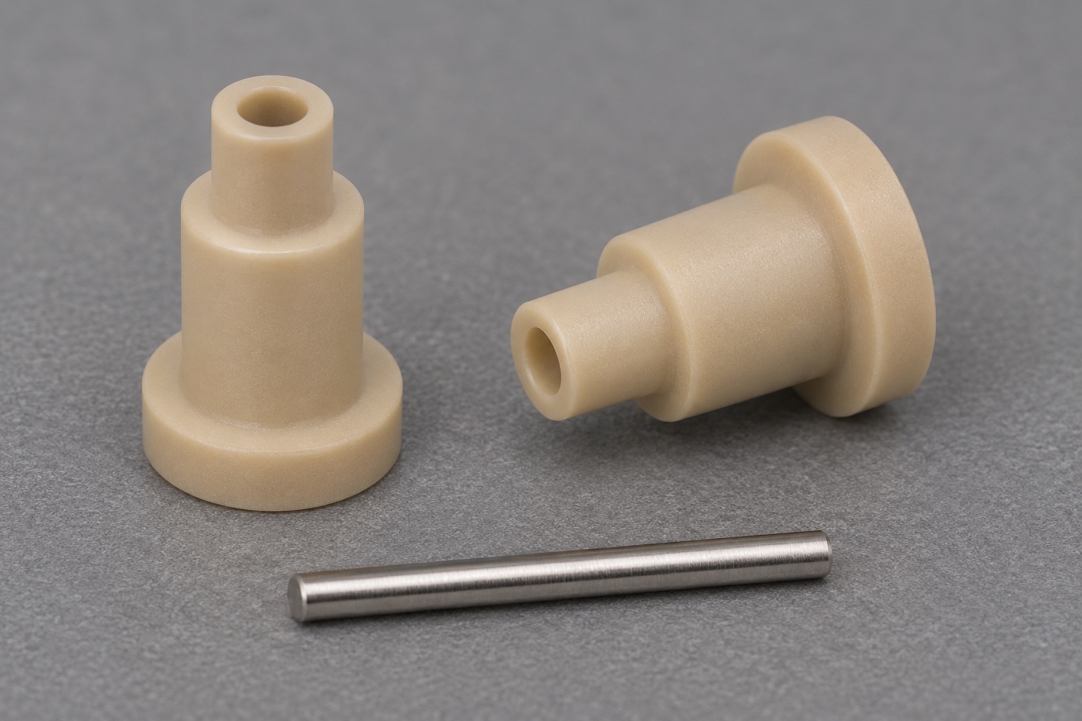
Start with the ferrule's mechanical role
PEEK CNC machining for an endoscope light-guide ferrule requires a clear definition of the mechanical interface. A small tubular sleeve may locate a separate bundle or mating component, but the machining drawing must identify the actual bore, shoulder and exterior references. This guide discusses those geometric features in a generic design review. It does not establish optical throughput, electrical insulation, thermal safety or suitability for a particular endoscope. A polymer's material name is not a finished-device approval. Define what the supplier is expected to manufacture and inspect before adding requirements that belong to an assembled light-guide system.

Choose the PEEK grade before assigning dimensions
State the polymer grade and stock form explicitly. Unfilled and reinforced PEEK are not interchangeable simply because both are sold under the same polymer family name. Their machining response, appearance and application requirements can differ. If a grade is already specified by the product owner, do not substitute another stock without approval. Identify the supplier documentation and any permitted processing history needed for traceability. A general statement that a material is used in medical applications does not establish that a particular stock shape or finished ferrule meets the intended requirements. Keep that distinction visible in the drawing review.
Put the bore and shoulder in one reference system
Decide which feature locates the ferrule in the mating assembly and which face controls insertion depth. Then define the bore axis and shoulder relationship using that datum structure. A drawing with independent size tolerances on every diameter can still leave the relationship between them unclear. Do not use a loose inspection pin as an undocumented substitute for a geometric reference. If different portions of the bore perform different functions, show their functional lengths. The inspector needs to distinguish an entry relief from a locating surface and a cosmetic face from an axial stop before selecting a measurement strategy.
Design thin walls for cutting and inspection access
Review the annular wall, shoulder transition and unsupported nose together. A narrow sleeve may distort under clamping or measurement even when the original stock is rigid enough to handle. Identify where the part can be supported without loading its functional wall. Internal radii and entry details should be compatible with practical tools and should not be left as mathematically sharp corners by default. If the drawing leaves insufficient access for either machining or inspection, resolve the geometry before production. Adding a difficult tolerance to an inaccessible feature does not create a reliable manufacturing or acceptance method.
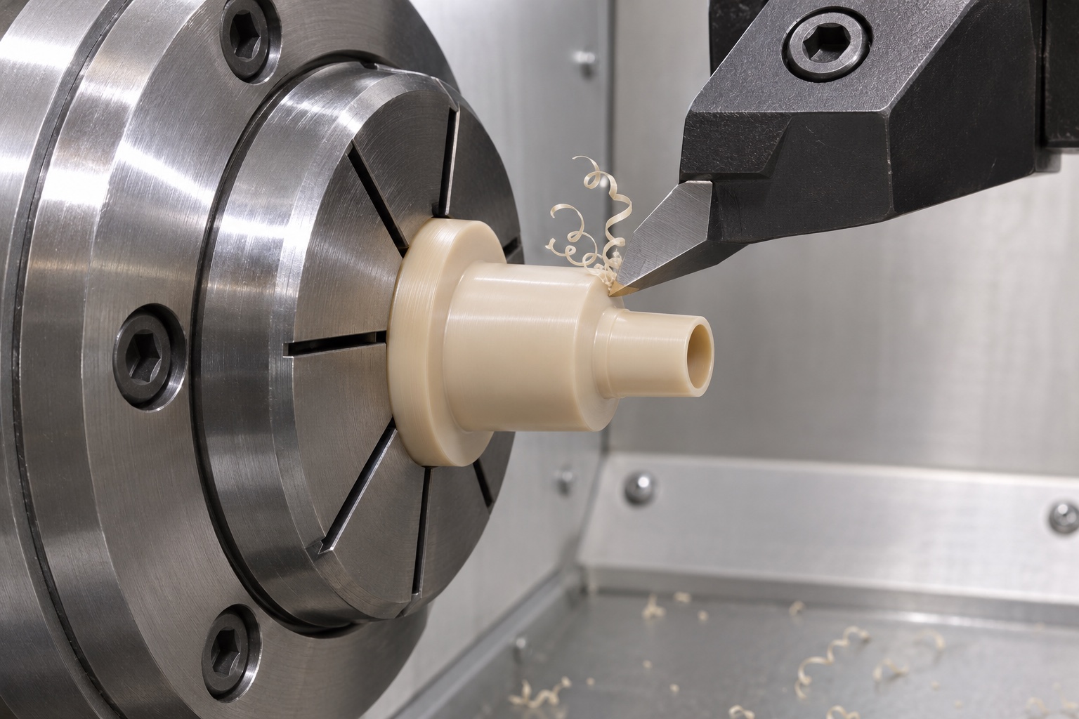
Plan roughing and finishing as controlled stages
A proposed turning sequence should remove material while retaining adequate support around the bore and shoulder. Review the effect of cutting heat and stock condition before choosing the final sizing sequence. If a conditioning or stress-relief step is proposed, obtain approval for its grade-specific procedure and its position in the route. Do not invent a universal heat-treatment schedule for every PEEK part. Leave the required allowance for finishing and define the state in which the finished dimensions apply. The goal is a reproducible process and inspection condition, not a part that happens to measure correctly immediately after one warm cutting pass.
Support the ferrule without squeezing it into shape
Choose workholding that locates on a suitable exterior region and supports the component without hiding the relevant features. Soft jaws, a collet or a purpose-made fixture can be considered, but suitability depends on the actual geometry and clamping load. Check the component again after releasing it from the fixture. A diameter produced while the wall is distorted can change when the part is free. The setup plan should state where contact occurs and how orientation is controlled. Do not assume a successful clamp trial on a thicker blank establishes the same behavior after the wall has been thinned.
Control bore entries and the axial stop
Separate the entry chamfer, cylindrical locating length and shoulder face on the drawing. A generous hand-deburred edge can shorten the functional bore or change how a mating part seats. Use an approved edge-finishing method that avoids smearing or raising material at the entrance. Inspect the shoulder and bore after that operation, not just before it. If a pin seems to stop early, identify whether the contact is on an edge, a local burr or the intended axial stop. Forcing the pin through can damage the very surface being checked and turn an inspection problem into a component defect.
Inspect bore alignment under defined conditions
Allow the part and measuring equipment to reach the inspection condition specified by the plan. Measure accessible bore sections and evaluate their relationship to the chosen exterior and shoulder references. A small flexible polymer sleeve may need low-force or optical methods for some features; the method must be appropriate to the required characteristic. Record the support arrangement and any contact-force concern. A pin that enters is a useful local observation but does not by itself establish bore-axis alignment or shoulder perpendicularity. Report which geometric relationships were measured instead of labeling a fit trial as a complete dimensional inspection.
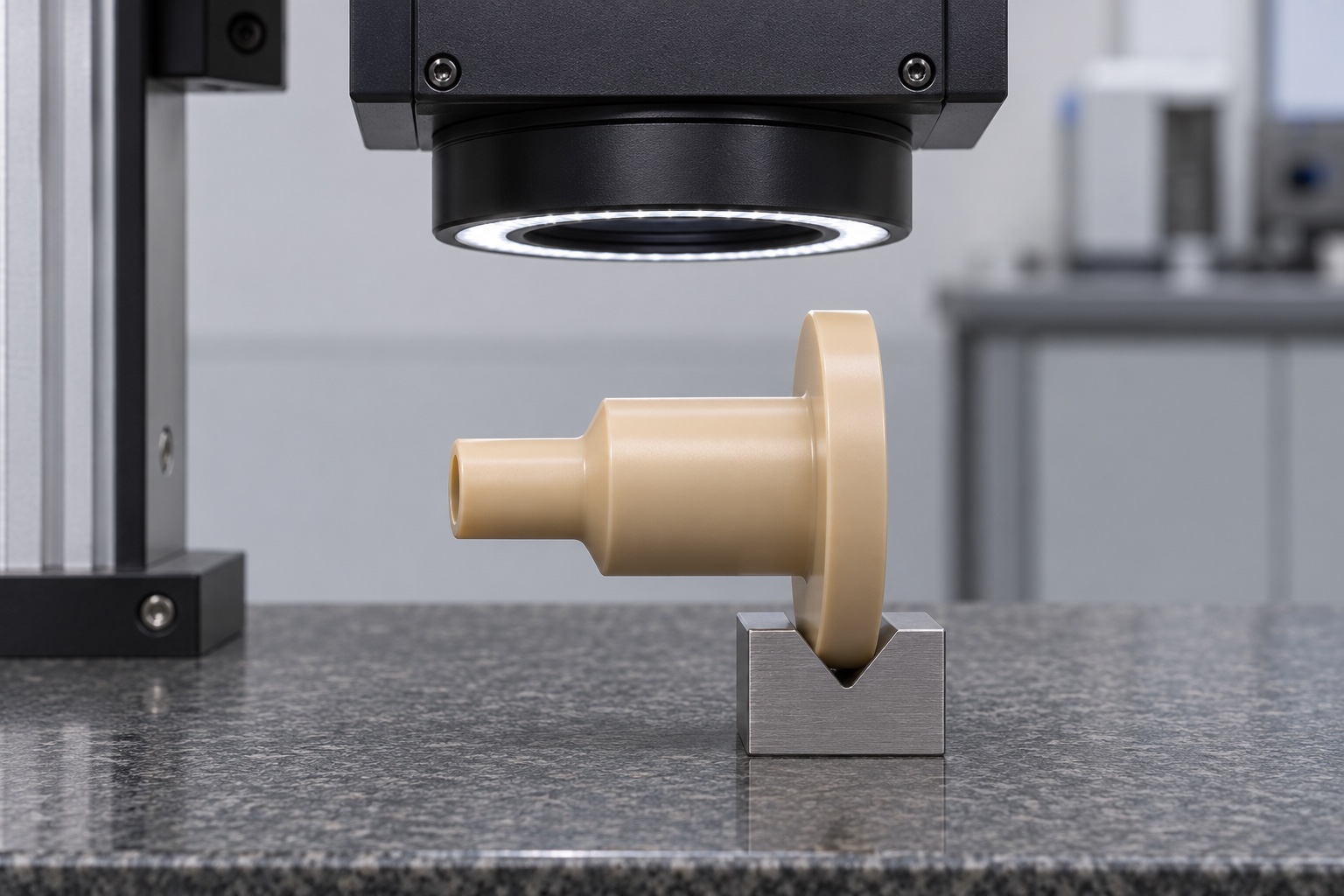
Distinguish finish requirements from optical claims
The ferrule's machined surfaces should meet the drawing's defined finish and defect requirements. That does not make the sleeve an optical test artifact or prove how a light-guide assembly will perform. Specify which surfaces require roughness evaluation and confirm the method can reach them. Avoid treating a matte appearance as a measured roughness value or a polished face as evidence of transmission efficiency. If an adhesive, coating or assembly process is involved, its requirements belong in the released design package. Machining acceptance should not quietly absorb compatibility decisions that the component drawing has never defined.
Investigate a fit problem before changing the bore
When an identified inert mating reference does not seat, inspect the references and the condition of both parts before rework. Check entry edges, bore location, shoulder depth and support-induced distortion. Record where contact occurs and whether it changes when the ferrule is released from its holder. Enlarging the whole bore may remove a symptom while destroying the locating relationship. Seek approval for corrections affecting the design and repeat all affected checks afterward. A dry bench fit does not authorize installation in an endoscope or establish behavior under illumination, temperature exposure, cleaning or repeated service.
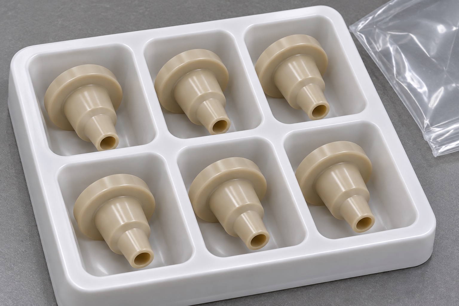
Package thin polymer features without preload
Keep parts separated and support them at robust regions rather than pushing foam into the bore or bending the narrow nose. Avoid closures that leave residue or exert an uncontrolled radial load. The packaging specification should say whether individual bags, inserts and labels are permitted. Maintain stock and revision identity through handling without placing an unapproved mark on a functional surface. Ordinary protective packing does not imply sterile delivery, validated biocompatibility or a cleanroom classification. The receiving team should be able to remove the component, identify its record and repeat the agreed inspection without first recovering it from packaging deformation.
Request evidence that matches the drawing
A useful request for custom PEEK light-guide ferrules includes the grade, drawing revision, quantity, datum structure, critical bore and shoulder requirements, finish condition and inspection deliverables. Identify any thin-wall feature that needs a support or measurement review before quotation. Ask how the supplier will verify the relationship that matters, rather than requesting uniformly extreme tolerances on every surface. Separate prototype geometric acceptance from approval of the eventual medical assembly. This produces a clearer technical discussion and a more meaningful first-article record while avoiding promises about optical or clinical performance that machining evidence alone cannot support.
FAQ
Can any PEEK grade replace the specified stock?
No. Use the approved grade and stock specification. Changes need review because reinforcement and processing history can affect the finished component and its requirements.
Why measure the ferrule after releasing the fixture?
Clamping can change the shape of a thin wall. Free-state checks help distinguish the actual geometry from a shape created by the holder.
Does a passing pin prove bore alignment?
No. A pin checks a particular fit condition. Axis relationships and shoulder geometry need their own defined measurement methods.
Is a universal annealing schedule suitable?
No. Any conditioning or stress-relief step must follow an approved procedure appropriate to the grade, stock and component, with dimensions verified at the required stage.
Does this guide establish optical performance?
No. It addresses machining and dimensional inspection. Optical, thermal and assembled-device requirements need separate evaluation.
What should accompany a first-article request?
Provide the controlled drawing, PEEK grade, critical characteristics, inspection conditions and acceptance deliverables, together with any downstream processing and handling requirements.

tanghangyun@oemach.com