
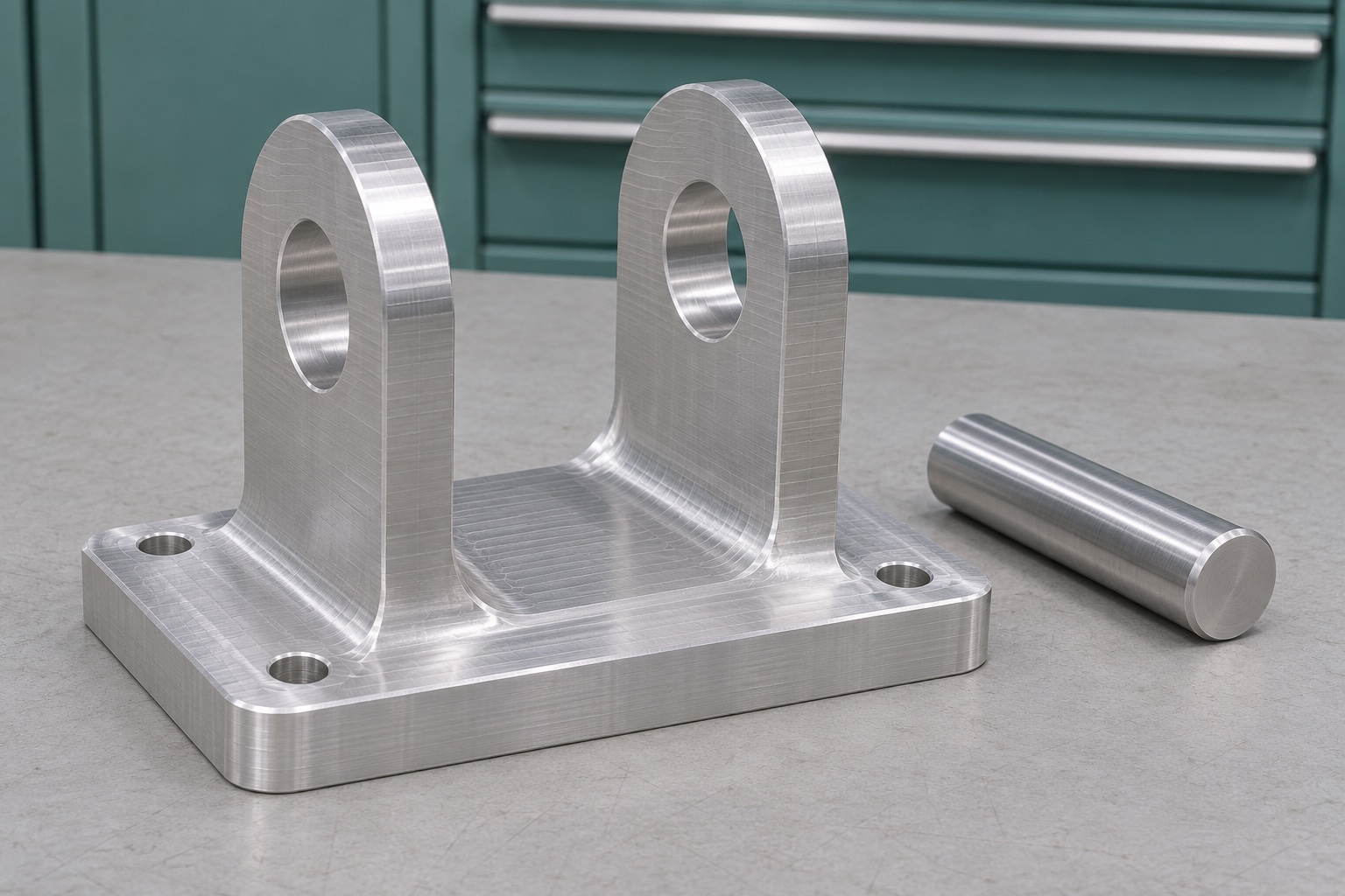
Define the bracket rather than the complete support system
6061 aluminum CNC milling for a medical cart monitor tilt bracket involves more than producing two holes in a fork. The pivot bores, opposing shoulder faces and mounting plane determine how the separate parts can be assembled. This guide considers those geometric relationships in a generic bracket. It does not establish a safe monitor load, holding torque, cart stability or suitability for clinical service. A component can meet its drawing and still need additional system-level evaluation. Before machining, separate the dimensions the supplier can verify from the structural and safety requirements that belong to the approved support-system design.

Identify the mounting plane and pivot axis
Choose the actual seating surface that locates the bracket on its support. Define the pivot axis relative to that surface and to the mounting pattern. If two ears carry the same pin, state how their bores relate; correct diameters alone do not guarantee a usable shared axis. The drawing should distinguish fastening clearance from a locating reference. A screw hole does not become a precise datum merely because a screw is tightened in it. An inspector needs a reproducible setup that represents the specified reference system rather than whichever surface happens to rest flat on the inspection table.
Specify the 6061 condition and finished state
Identify the aluminum alloy, temper and stock form required by the drawing. These are design inputs, not details to infer from a silver-colored component. If a surface treatment is specified, identify the dimensions and surfaces whose requirements apply after treatment. Masking, contact points and protected fits need review where they affect the geometry. This guide does not select a coating for clinical use or claim a particular treatment was performed. A supplier should quote the machining and finishing route against the actual specification, including any intermediate inspection needed before a later process makes a feature more difficult to measure.
Review fork spacing and tool access together
The gap between the ears needs enough space for the intended mating component and for the tools that finish the inner faces. Identify which faces set the axial stack and which simply provide clearance. Internal corners should be compatible with practical cutters unless a separately specified process is required. A deep narrow pocket may restrict tool stiffness and inspection access. Resolve those concerns while the design is still being reviewed. The drawing should not demand an inaccessible sharp corner merely because it was easy to model. Functional intent is better preserved by a reviewed radius than by an ambiguous shop-floor interpretation.
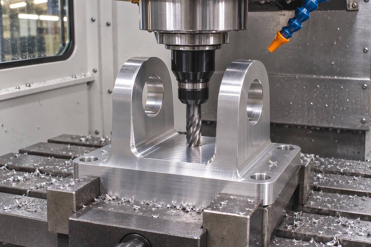
Rough the stock without losing support
Plan rough milling so the component retains suitable support while the ears and mounting region are formed. Removing a large pocket or thin section can change the part's response to subsequent clamping. Define which surfaces remain for locating the next operation and where clamps can apply force without bending the fork. The route should distinguish roughing from the passes that establish final face spacing and bore references. It is not enough to measure a clamped bracket once and assume the free-state geometry is identical. Review the setup after release, especially where the remaining structure is less rigid than the original blank.
Plan the two pivot bores as a related feature set
Decide whether the geometry and equipment allow both bores to be finished from a common setup. A suitable boring or reaming route may help preserve the shared reference, but no tool choice automatically guarantees alignment. Long tool reach, access through the first ear and the state of the second ear require review. If the part must be repositioned, show how the original datum is recovered. Do not use a passing assembly pin as the only evidence for the relationship. The process and inspection plans should name the axis requirement rather than describing the objective simply as making the pin slide through.
Control the shoulder faces and axial stack
The opposing faces can affect the available width for bushings, washers or other mating components, depending on the actual design. Specify the required separation and relationship to the pivot axis. Treat a counterbore, spotface or edge break as its own feature rather than including it accidentally in a face measurement. A bracket may have aligned bores yet still interfere because its face spacing is wrong. Conversely, a wide gap does not establish a correct axial stack. The supplier should not invent washer thicknesses or tightening instructions to compensate for a drawing that leaves the functional faces undefined.
Inspect geometry before assessing movement
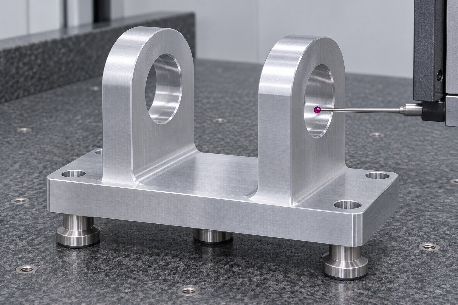
A proposed dimensional inspection checks the mounting plane, hole pattern, individual bore sizes, required axis relationship and shoulder spacing. Use measurement methods that can reach the specified features and establish the drawing's datums. Inspect before a dry assembly trial so a fit observation can be interpreted against known geometry. If a coordinate measuring machine is used, its probing plan must represent the relevant bore length and face regions rather than collecting convenient points only. The report should distinguish measured characteristics from observed fit, and should identify the condition in which the part was supported during each check.
Check a swept envelope with an inert fixture
An unloaded engineering fixture can use an identified dummy plate and reference pin to examine geometric clearance through a defined movement range. Observe intermediate positions, not just the two endpoints. Record any contact and the support condition. This does not establish friction torque, retention, fatigue strength or safe support of a real monitor. Do not mount an unapproved bracket on a working medical cart for an improvised load trial. Any structural, stability or user-safety evaluation requires the appropriate system design, controlled procedure and acceptance criteria outside the scope of a dimensional machining guide.
Diagnose binding without hiding the cause
If the dummy assembly binds, first confirm the identities and condition of the pin, mating piece and bracket. Check bore alignment, local edges, face spacing and fixture distortion. Record where contact occurs before changing anything. Enlarging both holes may remove resistance but destroy the intended relationship or clearance. Approved rework should identify the cause and the characteristics that need reinspection. A passing second trial is not meaningful if the setup or reference parts changed without being recorded. Keeping dimensional evidence and assembly observations separate makes it easier to determine whether the problem belongs to machining, another part or the test fixture.
Protect functional faces after finishing
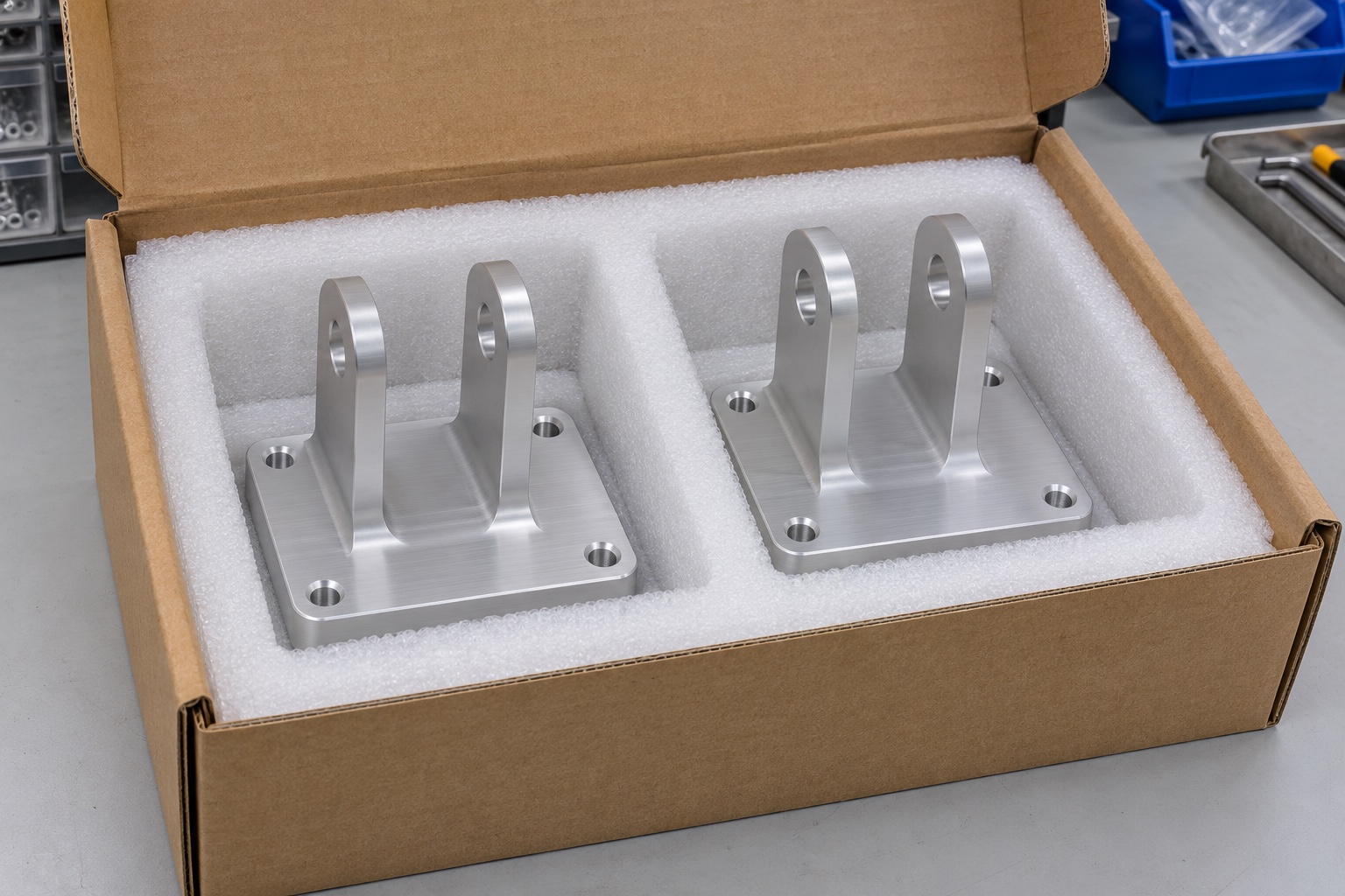
After the specified final process, keep pivot bores, inner shoulders and the mounting plane protected from contact damage. Use packaging that supports robust regions rather than forcing the ears together with a tight insert. Keep bracket identity and revision associated with the inspection records, particularly when several similar sizes are handled. Ordinary protective packaging does not establish sterile delivery or a medical approval. If marking is required, identify a permitted location instead of placing it on a functional seat. The receiving team should be able to inspect the part without finding that its reference surfaces were damaged by packing or identification.
Write a drawing-led manufacturing request
A useful request for a custom medical cart tilt bracket includes the drawing, alloy and temper, quantity, finish state, pivot-axis requirements and face-spacing requirements. Identify the mounting reference and any first-article records that must accompany the batch. If a tight relationship is difficult to inspect, resolve that before purchase rather than accepting a generic statement about precision. Separate the component's geometric acceptance from approval of the monitor support system. This helps a CNC supplier propose a practical route and report the evidence it can actually provide without inventing load ratings, device compatibility or certification claims for the finished assembly.
FAQ
Do correct pivot hole diameters guarantee alignment?
No. Individual size checks do not establish the required relationship between the two bore axes. Define and inspect that relationship separately.
Can one machining setup eliminate all error?
No. A common setup can reduce reference transfers, but tooling access, deflection and inspection still need review against the drawing.
What should be specified for 6061 stock?
Identify the required alloy, temper, stock form and documentation, plus the final treatment state in which critical dimensions apply.
Does an unloaded movement check establish load capacity?
No. It can reveal geometric interference in the defined fixture. Structural strength, holding torque and cart stability require separate evaluation.
Why inspect the inner shoulder spacing?
It controls a different part of the axial assembly than the bore diameters. Aligned bores can coexist with incorrect face spacing.
Should a binding pivot be corrected by enlarging both holes?
Not without an approved disposition. First inspect references, edges, alignment and mating parts, then recheck every characteristic affected by a permitted correction.

tanghangyun@oemach.com