
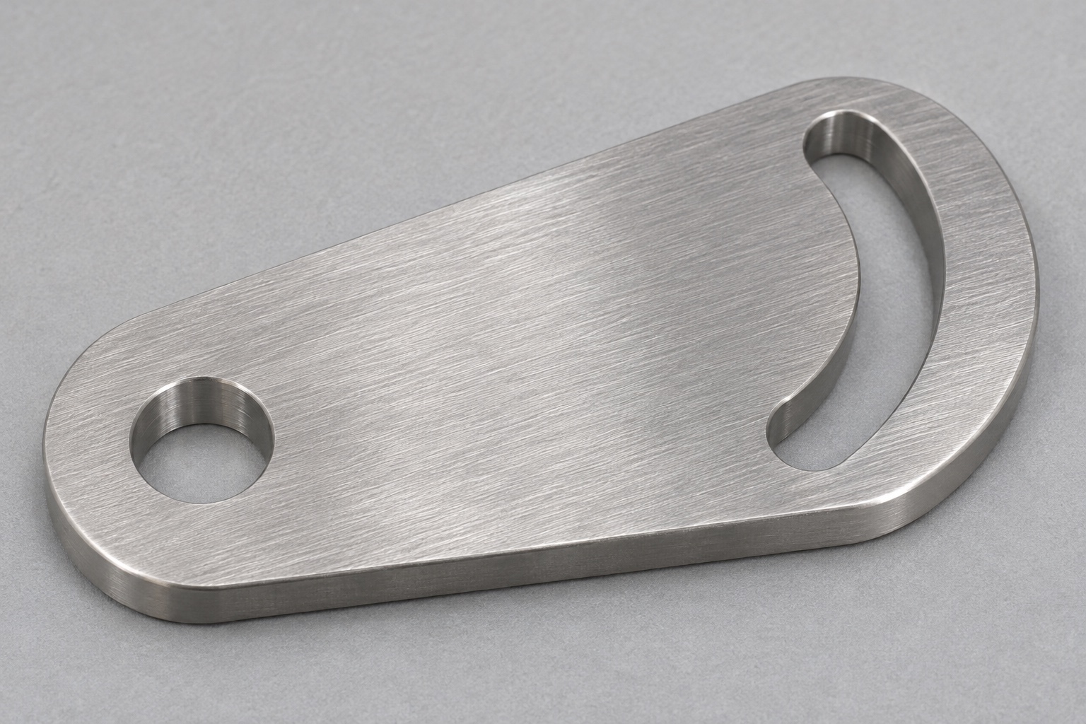
Define a component inspection task
316L CNC milling of a centrifuge lid-latch cam plate starts with a controlled geometric requirement. A flat plate can have a pivot bore, a curved follower slot and locating faces, each with a different role in the drawing. This guide explains how to plan their machining and dimensional inspection for a generic medical laboratory component. It does not establish centrifuge compatibility, lid retention, interlock operation or safe operation at speed. Keep the machining discussion separate from the complete latch and control system. A supplier needs an approved component specification, not an instruction to infer safety requirements from the part's name.

Make the pivot reference explicit
Decide whether the pivot bore locates the part or merely provides clearance around a separately located bearing. Identify the relevant plate face and the feature that establishes angular orientation. Then relate the slot profile to those references. A correct slot width does not prove the slot is in the correct position around the pivot. Likewise, a visually symmetric plate does not establish the required angular relation. The drawing should let an inspector reproduce the datum structure without using a convenient exterior edge that was never intended to control the mechanism. Separate dimensional size from the required geometric relationship.
Specify the curved slot without ambiguity
Show the actual slot boundaries and how their profile is controlled relative to the reference system. If the slot is a constant-width circular path, define that geometry clearly; if it includes a transition or variable-width region, do not describe it with a single radius that omits the change. Identify whether end regions are functional or simply provide tool clearance. A model and drawing should agree on these details. Do not assume the outside silhouette controls the follower path. The supplier should be able to distinguish the surfaces that guide a reference from the surrounding material that only provides structural continuity.
Review stainless stock and surface condition
Specify 316L stock, thickness and any required material documentation before machining. A shiny metal plate is not evidence of its alloy identity. Identify later finishing or surface treatment separately and state the condition in which dimensions apply. If the supplier proposes an alternative stock form, review whether it changes allowance, support or the planned reference surfaces. Do not infer application suitability from the alloy name alone. For a component associated with medical laboratory equipment, cleanliness, chemical exposure and device approval may introduce requirements outside a general machining order. Those requirements need explicit design inputs rather than assumptions made by the machine shop.
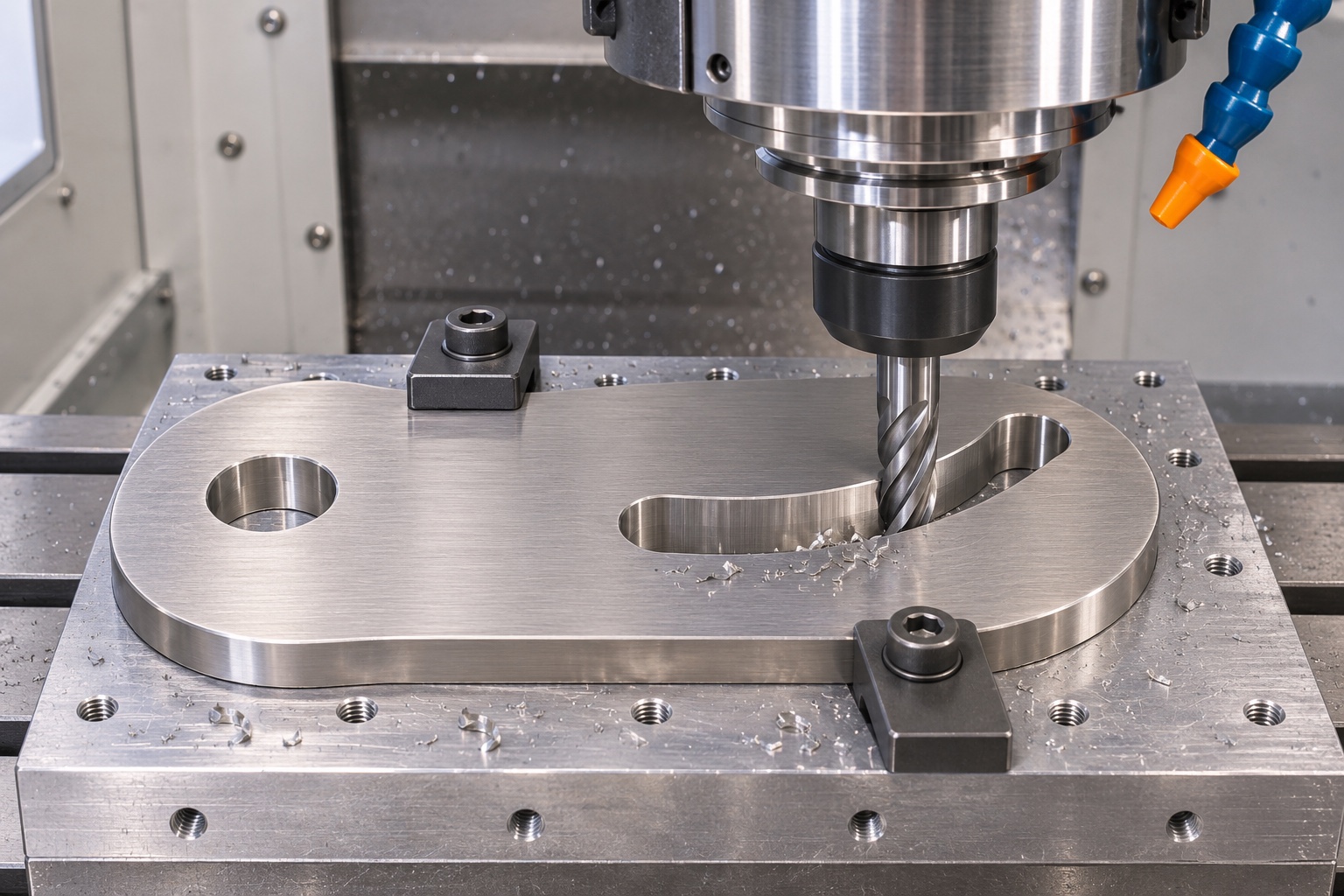
Support the plate through rough milling
Choose a setup that supports the plate near the cut without obstructing the slot or loading a thin remaining web. The original blank and the nearly finished part can behave differently under the same clamps. Plan roughing so adequate locating and supporting surfaces remain for the finishing stage. Where a through-slot opens onto a fixture, ensure the tool has the intended clearance and cannot cut an unapproved support. The setup sheet should show actual contacts and orientation. Do not accept the free-state shape merely because a clamped plate lies flat during cutting; inspect the required condition after release from the fixture.
Plan the pivot bore and slot as related features
Consider whether the pivot and follower geometry can be finished while preserving a common reference. A shared setup can reduce transfers, but it does not eliminate tooling errors or the need for inspection. Review cutter access, engagement near the slot ends and the measurement access that remains afterward. If a second setup is needed, specify how the reference is recovered. The process should not treat a later fit trial as a substitute for maintaining the geometric relation. A reference pin sliding through the bore establishes only a local fit observation unless the rest of the datum structure is also controlled.
Finish slot walls and edges deliberately
The slot's functional wall is not the same feature as its entry chamfer. Specify an allowed edge condition that removes prohibited raised material without changing the guided profile. Identify any region where an edge break must remain limited. A generic instruction to polish everything can change the follower contact and shorten the useful wall height. Review access to both sides of the through-slot, including the exit side. After finishing or approved deburring, inspect the affected profile again. A smooth feel at the entrance does not establish the condition of the full wall or the geometry at the curved end.
Inspect the profile in the drawing's reference system
Plan the measurement method before assigning acceptance. A coordinate measuring machine or an appropriate optical method may be useful, depending on access and the specified characteristic. Record how the pivot, plate face and angular reference are established. Inspect defined regions of both slot walls rather than only the easiest points to reach. Where the drawing requires a profile relationship, do not substitute a few width measurements and label the whole path accepted. Also distinguish entry edges from the functional wall. An inspection report should make clear which surfaces and positions were evaluated and which features require another approved method.
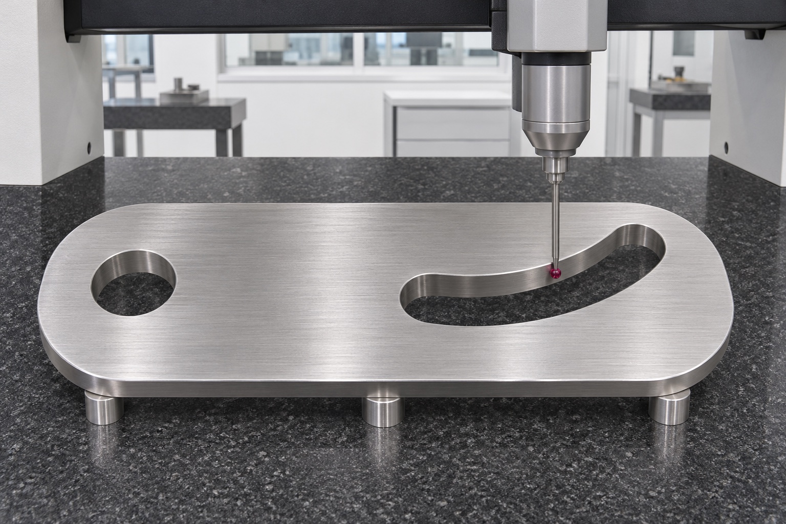
Separate plate thickness and flatness from slot fit
The plate's thickness, seating condition and slot geometry can affect different parts of an assembly. Correcting one does not automatically correct the others. Measure the required face condition in the specified support state and report local damage or raised material separately. If the plate rocks on the inspection fixture, determine whether the cause is the part, a burr, debris or the support arrangement before interpreting a profile result. A thickness measurement at one convenient corner cannot establish every face requirement. The inspection plan should identify the characteristics that are independent so a passing follower trial is not used to cover unmeasured geometry.
Use inert references only for a defined geometry check
A separate unloaded fixture can use identified pivot and follower references to observe contact along a prescribed path. Record the support, orientation and observation positions, including intermediate portions of the curve. This is not a test of latch security, motor control or centrifuge operation. Do not modify a working latch or defeat an interlock to perform a machining check. Any equipment-level evaluation needs the responsible owner's approved process. The useful output from the bench fixture is a documented geometric observation under known conditions, interpreted alongside the measurements rather than promoted into evidence of operational safety.
Control corrections and protective handling
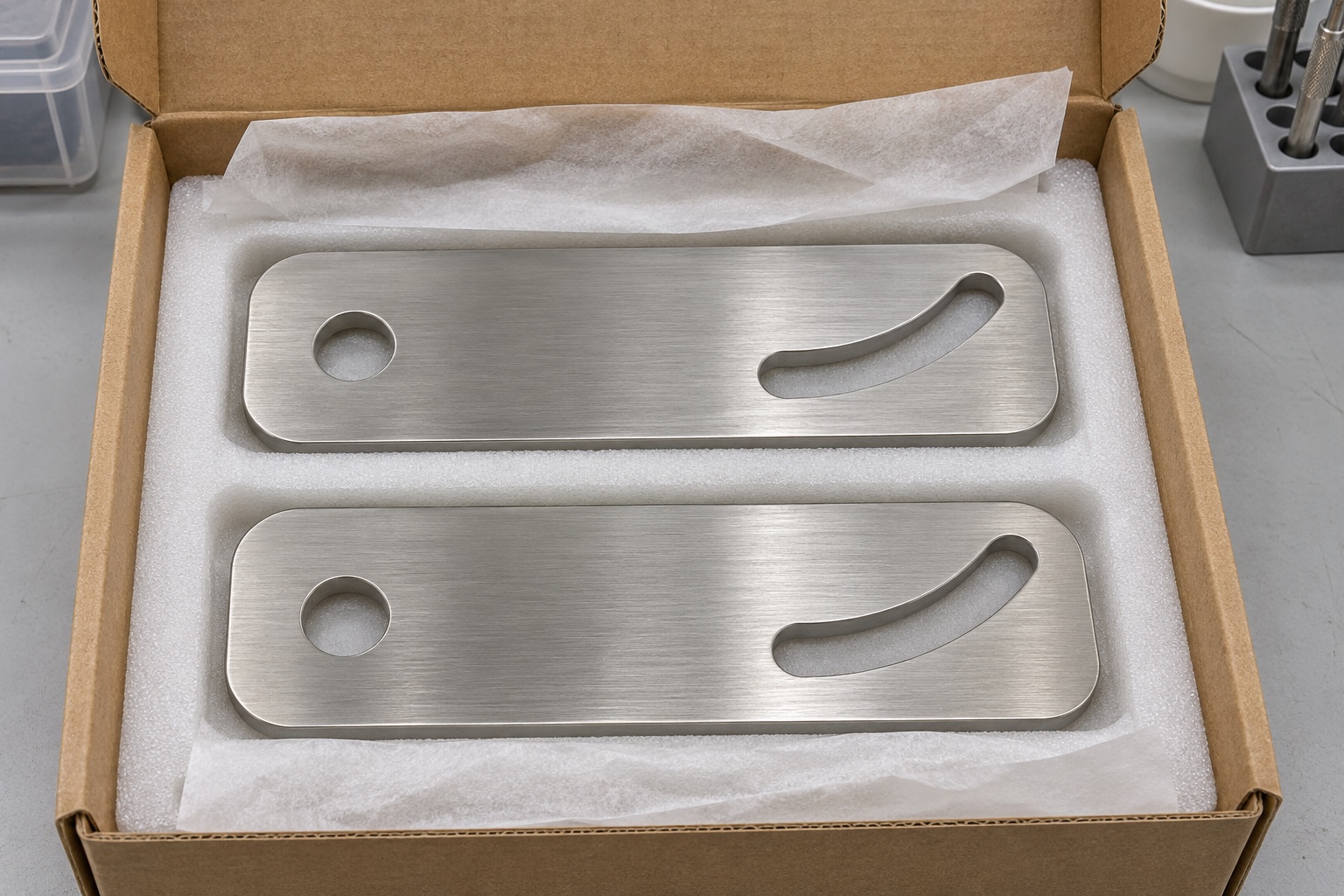
If a follower reference binds, preserve the observation and inspect references, wall condition and fixture support before changing the slot. Enlarging the path until motion becomes free can destroy the intended profile. Approved rework must identify which dimensions and geometric relationships are affected and what must be checked again. After final acceptance, separate plates so their faces and slot edges do not strike one another. Packaging should protect geometry without bending the plate or leaving unapproved residue. Ordinary protective packing is not evidence of sterile delivery, and the component's identity should remain associated with its actual inspection record.
Prepare a drawing-led machining request
A useful request includes the controlled model and drawing, 316L material requirement, quantity, datum scheme, slot profile requirements, edge condition and final finish state. Identify the inspection deliverables for the pivot, curved path and plate faces. Ask the supplier to review access and reference transfers before committing to the route. For a first article, agree how findings and proposed corrections will be reviewed before a batch proceeds. This produces a meaningful machining discussion without inventing a load rating or safety claim. Component acceptance remains tied to the released specification; approval of the complete centrifuge mechanism remains a separate responsibility.
FAQ
Does a correct slot width prove the whole profile?
No. Width is a local size characteristic. The path and its relationship to the pivot and angular references need the inspection required by the drawing.
Which references should locate the cam plate?
Use the drawing's defined pivot, face and orientation features. Do not substitute a convenient external edge unless the approved datum scheme permits it.
Can the slot be enlarged when a follower binds?
Only with an approved disposition. First examine the reference parts, edge condition, measured profile and fixture support, then repeat the affected checks after permitted rework.
Does a common machining setup guarantee accuracy?
No. It can reduce reference transfers, but tooling, support and the resulting geometry still need review and dimensional evidence.
Can a bench fit prove centrifuge latch safety?
No. The unloaded check addresses selected geometry only. Latch retention, interlock behavior and operating safety require separate equipment-level evaluation.
What should accompany a first-article request?
Provide the drawing revision, material, critical profile and bore requirements, inspection conditions, finish state and the deliverables required for component acceptance.

tanghangyun@oemach.com