
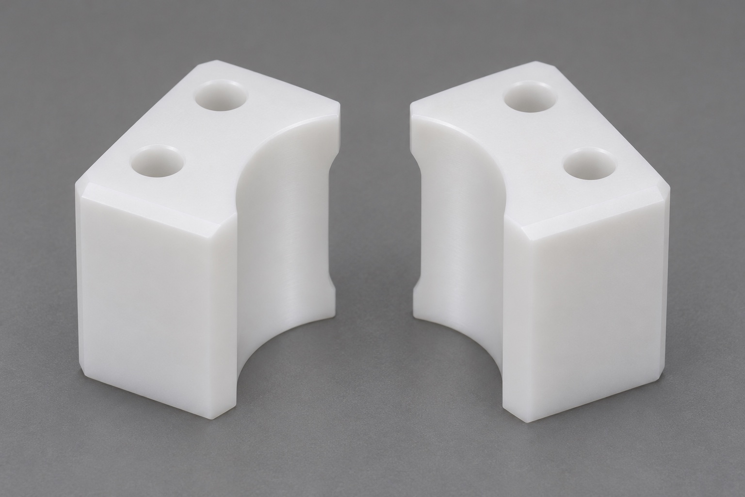
Define what the jaw actually contacts
POM-C CNC machining for tube decapper jaw inserts begins by identifying the interface. A jaw might contact a cap, a tube body or a separate fixture reference; these are not interchangeable requirements. The drawing must identify the intended object and the portion of its envelope used in the design. This guide addresses machining and geometric inspection of generic concave inserts for medical laboratory automation. It does not establish removal torque, grip reliability, sample integrity or suitability for a particular tube. Use inert references for engineering checks, and keep component dimensions separate from the qualification of a complete automated decapping process.

Specify acetal stock rather than appearance
Identify POM-C grade, stock form and any documentation required for the order. A white polymer block is not enough to establish the material or its history. Do not substitute POM-H or another polymer simply because it machines similarly or appears suitable. If the application has chemical exposure, cleanliness or other compatibility requirements, they must be supplied by the responsible design owner. A general material description cannot establish them. Keep stock identity connected to the manufactured inserts, especially where several similar jaw designs are handled together. Changes in stock or processing should be reviewed against the actual requirements before production.
Relate the contact profile to the mounting seat
The mounting seat and locating features establish how an insert sits on its carrier. Define the concave profile relative to those references rather than only dimensioning its radius. Its center, axial height and orientation can matter independently of the local curve size. If screw holes merely provide fastening clearance, do not use them as precise locating references without a drawing requirement. Identify any separate locating shoulder or pin feature. The inspector should be able to reproduce the relationship using a suitable fixture without guessing the installed position from the outer block shape or the appearance of a matched pair.
Describe the useful contact region
Specify which part of the groove is intended to contact the defined reference and which regions provide clearance. An entry chamfer, relief or decorative edge should not be included accidentally in a profile measurement. If the design calls for texture, grooves or another surface feature, state it explicitly and review the inspection method. Do not add teeth because a drawing seems to need more grip. The manufacturing supplier should not invent a contact pattern to compensate for an unresolved application requirement. A smooth generic concave insert and a textured production jaw are different designs, even if their main radius is similar.
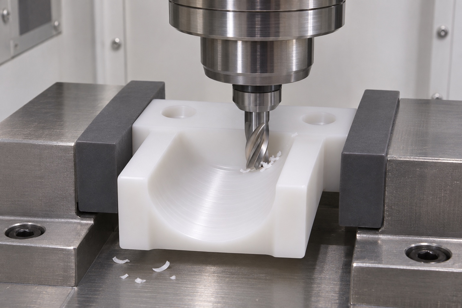
Plan milling with adequate support
Review the stock orientation, locating surfaces and support before cutting the concave face. Remove material in a sequence that preserves a stable mounting reference. Thin edges around the groove and recesses near fasteners can be more vulnerable than the original blank. A setup that holds the rough block securely may distort the finished insert if the same force is applied later. Show where the part is supported and how it is located after transfer. Select tools and cutting conditions for the actual stock and geometry rather than assuming a universal feed or speed. The process should avoid making a fixture-induced shape look like the accepted free-state part.
Control holes, recesses and edge details
Separate fastening-hole size, head recess geometry and any locating feature on the drawing. A screw head seating correctly does not prove the jaw's contact profile is in position. Review whether the remaining material around a recess provides adequate support during machining and inspection. Edge finishing should remove prohibited raised material without changing the useful profile or shortening a locating shoulder. After an approved finishing operation, inspect affected features again. If a tool or measuring probe cannot reach a specified region, raise that access problem during design review instead of accepting the region by appearance or by the fact that a screw can be inserted.
Establish the measurement condition
Let the part and measuring system reach the condition required by the inspection plan. Record how the insert is supported and whether a characteristic is evaluated in the free state or a defined mounted state. Use a measurement method suited to the polymer, feature and required uncertainty; avoid an uncontrolled contact force that changes the surface being measured. An appropriate optical or low-force contact method may be useful, but its suitability follows the actual characteristic. A radius measurement taken at one section does not establish the profile's position, orientation or consistency across the whole useful contact region.
Inspect individual inserts before the pair
Measure each insert's mounting references, hole pattern and concave profile before interpreting a combined fit. This helps distinguish an individual component error from a carrier or assembly problem. If the design calls for left and right parts, preserve their identities throughout the inspection record. Do not assume two visually mirrored pieces are interchangeable or that every insert in a batch must be matched to one partner. Pairing is a design and order requirement. The report should state which parts were measured, which references were used and which relationships were evaluated only after the separate components were mounted together.
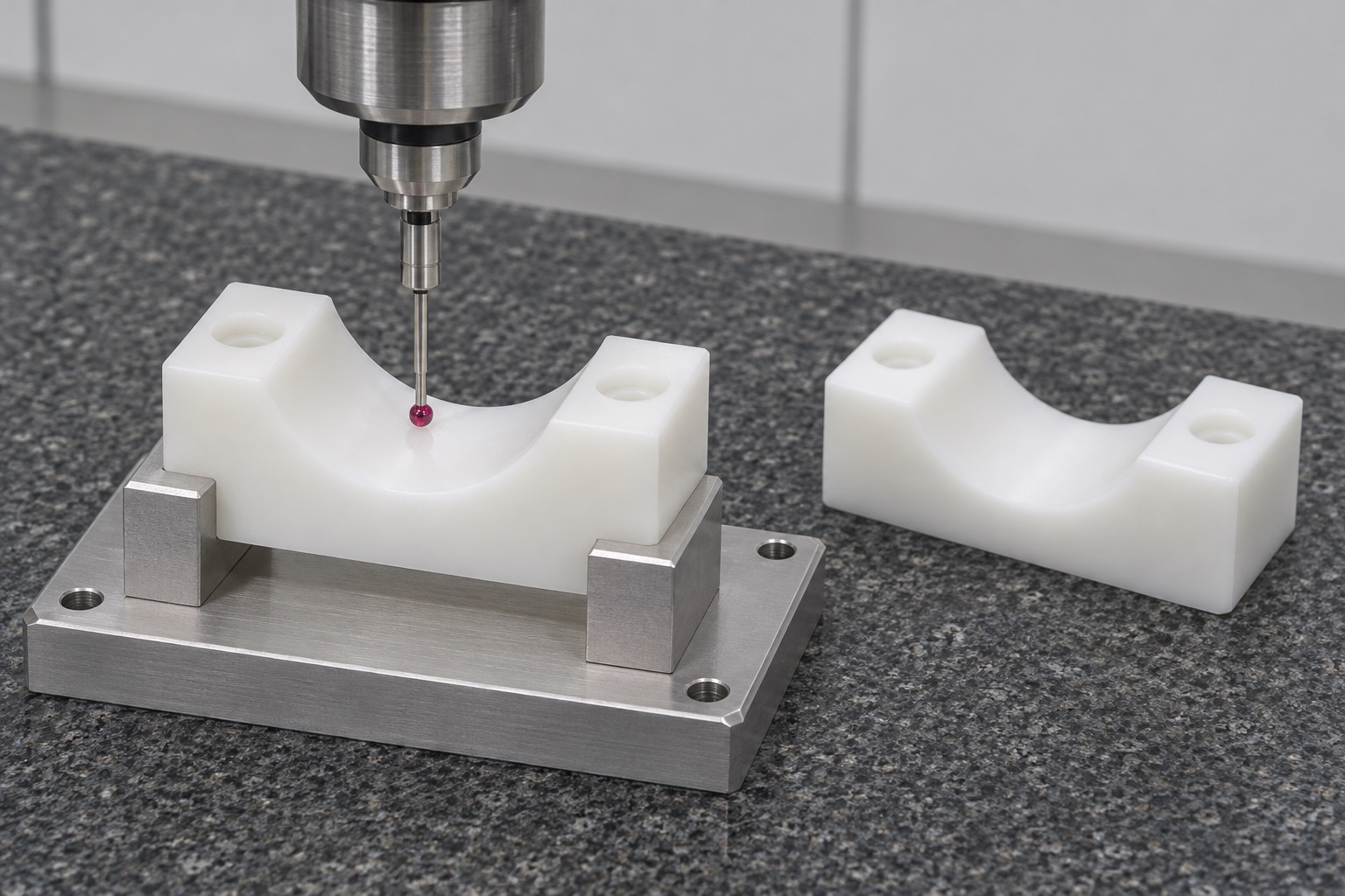
Check pair alignment with inert references
An unloaded bench fixture can position two identified inserts and an inert reference to observe relative height, approach clearance and contact location. Define the fixture and the observation positions before comparing results. Do not use a biological sample, a pressurized vessel or an operating decapper as a substitute for that engineering setup. A visible contact patch or a successful dry approach does not establish removal torque, reliable cap retention or safe handling of real specimens. The useful result is a documented geometric observation under the stated conditions, interpreted together with the dimensional inspection and the actual interface requirements.
Diagnose unequal contact before changing the grooves
If one insert touches earlier than the other, check mounting seats, reference identity, orientation, profile position and carrier alignment. Preserve the observation before choosing a correction. Deepening both grooves until a reference appears centered may remove the symptom while changing the intended contact. If rework is approved, identify affected dimensions and repeat the relevant individual and pair checks. Also record whether the reference or support changed. A comparison is not reproducible if the second trial uses a different surrogate or mounting condition without documentation. The corrective action must follow the released design rather than a technician's preferred feel.
Protect profiles and preserve identification
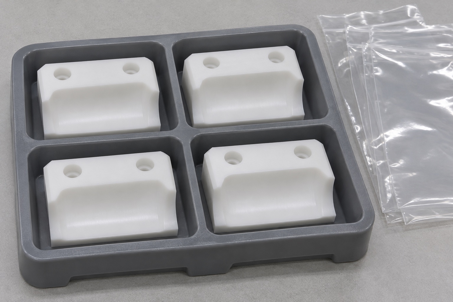
Store inserts separately so their concave faces and thin edges do not rub against other parts or absorb uncontrolled packing loads. Avoid stuffing material into the groove unless the handling specification permits it. Keep stock and revision identity associated with the inspection record, with left and right identity where required. Ordinary protective packing does not establish sterile delivery or compatibility with laboratory reagents. Cleaning requirements must be separately defined with appropriate acceptance evidence. The receiving team should be able to remove a part, identify its intended role and repeat the agreed geometric check without first discovering damage or mixed revisions.
Request a verifiable small-batch process
A useful machining request includes the controlled model and drawing, POM-C grade, quantity, mounting datum scheme, contact profile requirement, final surface condition and required inspection deliverables. Identify whether pairing, orientation marking or a mounted-state check is required. Discuss inaccessible features and support-induced deformation before placing a batch order. For a first article, agree how findings and proposed corrections will be reviewed. This lets the supplier propose a practical route and report evidence without inventing a cap-removal specification. Geometric component acceptance remains separate from approval of the automated laboratory workflow, which needs its own validated requirements and testing.
FAQ
Must the drawing say whether the jaw grips a cap or a tube?
Yes. The contact object, relevant envelope and useful profile region are design inputs. They should not be inferred from the name tube decapper.
Can POM-H replace POM-C without review?
No. Use the specified grade and stock requirements. A material substitution needs approval even when the two polymers appear similar.
Does a correct groove radius establish the jaw position?
No. The profile's location and orientation relative to its mounting references need separate requirements and inspection.
Must every two inserts be a permanently matched pair?
Only if the design or order requires it. Record left and right identity, pairing and interchangeability requirements rather than assuming them.
Does an inert reference test prove grip torque?
No. An unloaded geometry check cannot establish cap-removal performance, specimen safety or compatibility with real tubes.
How should unequal contact be investigated?
Check mounting seats, reference parts, orientation, profile measurements and carrier alignment before seeking approval for any change to the grooves.

tanghangyun@oemach.com