
Define the adapter as a mechanical interface
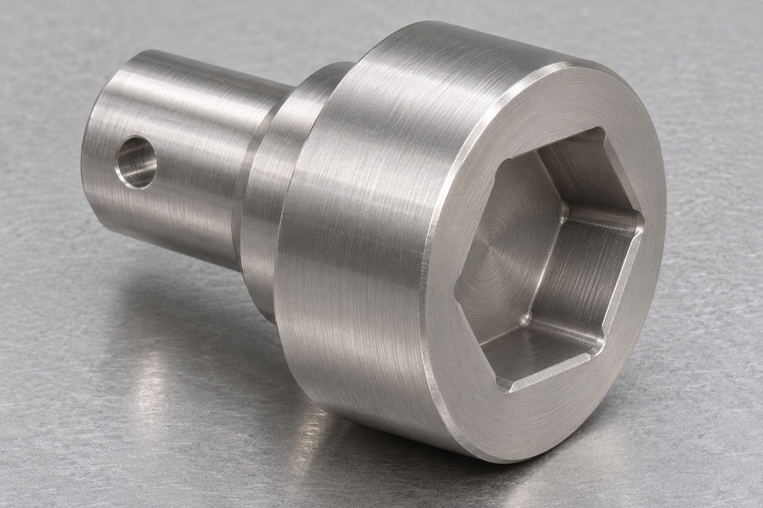
316L CNC machining of a cryovial capping spindle adapter concerns the interface between separately specified mechanical elements in laboratory automation. A stepped body may include a locating shank, an axial shoulder, a polygon socket and a transverse hole. This guide addresses how those features can be manufactured and inspected against a controlled drawing. It does not establish cap torque, vial compatibility, sample integrity or automatic capping performance. The word cryovial describes the intended application context, not proof that the adapter has been qualified for cryogenic exposure. Keep component acceptance separate from the approved operating process and from any claim about specimen handling.

Establish the shank axis and axial stop
Decide which diameter locates the adapter on the supporting mechanism and which shoulder defines its axial position. Identify the usable locating length separately from chamfers and reliefs. A dimension on the largest outside diameter does not necessarily define the working axis. Relate the socket and transverse hole to the actual locating reference rather than to a convenient exterior surface. The drawing should enable an inspector to recover the same reference without an unspecified assembly. If the interface uses an additional coupling or bearing, its requirements must be supplied explicitly instead of inferred from the component name or a photograph.
Specify the polygon socket's useful surfaces
Define the socket across its functional flats and identify the depth over which they apply. Separate the entry detail, side walls and bottom clearance. A reference can stop on an entry edge or pocket floor before reaching the intended seating condition. If the polygon provides an angular relationship to another feature, state that relation in the datum scheme. Do not treat a nominal hexagon as a complete specification of the interface. The supplier needs to know which surfaces locate or contact the mating reference, which provide clearance and which characteristics will be measured rather than judged by a trial insertion.
Review internal corners before choosing milling
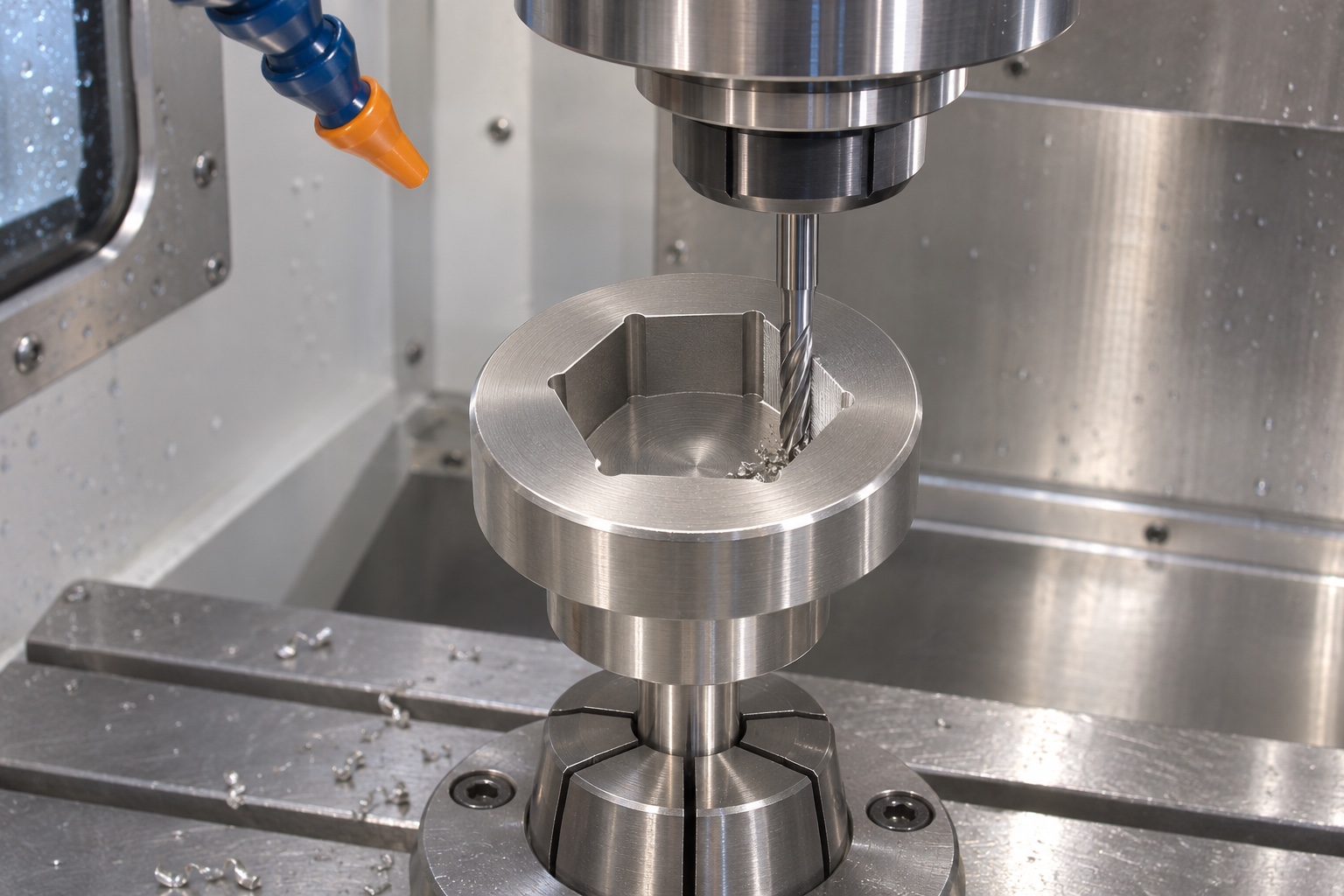
A rotating milling cutter leaves an internal radius. If a mating polygon needs additional corner clearance, review permitted reliefs or another approved manufacturing route. Do not silently enlarge the entire socket to make an unreviewed reference fit. Local reliefs must be defined so they do not remove a required contact region or reduce the intended wall section. The model and drawing should agree on those details. A photograph cannot distinguish a functional corner from an incidental tool mark. Resolve the corner condition before quotation, including how the inspector will evaluate the flats without accidentally measuring the relief instead.
Identify stainless stock and final surface condition
Specify the 316L designation, stock form and required material documents. Do not replace the alloy because another stainless grade appears similar or is easier to procure. Identify later surface treatment and cleaning requirements separately from the material name. If dimensions apply after a finishing process, say so in the manufacturing package. A bright surface is not proof of material identity, compatibility or a defined cleanliness level. This guide does not select a treatment for specimen handling. Any application-specific exposure or cleaning requirement must come from the approved design and have its own acceptance evidence, rather than being implied by the word medical.
Plan the turned features as a reference set
A proposed turning sequence should establish the shank, shoulder and accessible body features while retaining suitable support. Review workholding contact and the useful length left for the later socket operation. Excessive clamping or an unsupported projection can make the manufacturing state different from the inspection state. Select tooling and cutting conditions for the actual blank and geometry; no universal speed or feed is specified here. The process sheet should identify which reference surfaces are finished together and which remain to be completed after transfer. The purpose is traceable reference continuity, not an unsupported promise that one operation eliminates every error.
Transfer the reference to socket and cross-hole machining
The milling setup must recover the defined shank and shoulder references without damaging them. Specify how angular orientation is established before cutting a socket or transverse hole that has a clocking requirement. A drilled hole of the correct size can still be at the wrong height or angle. Review access for the drill exit and subsequent edge finishing. If the transverse feature intersects another cavity, identify that intersection explicitly. Do not assume every adapter has the same internal construction. The route should distinguish the operations and checks needed for the actual drawing from the generic shape shown in an engineering image.
Finish entries and intersections without changing fit
Define the allowed edge condition at the socket mouth and the cross-hole. Removing raised material must not shorten the useful flats, alter a seating shoulder or create a larger unapproved entry. Inspect affected geometry after any finishing step capable of changing it. A smooth feel at the mouth does not establish the condition deeper inside the socket. If access prevents direct inspection of a specified region, resolve the method before production. The supplier should not use a passing pin or polygon reference to accept every unseen feature automatically. Each local check has a limited purpose that belongs in the inspection plan.
Measure relationships as well as individual sizes
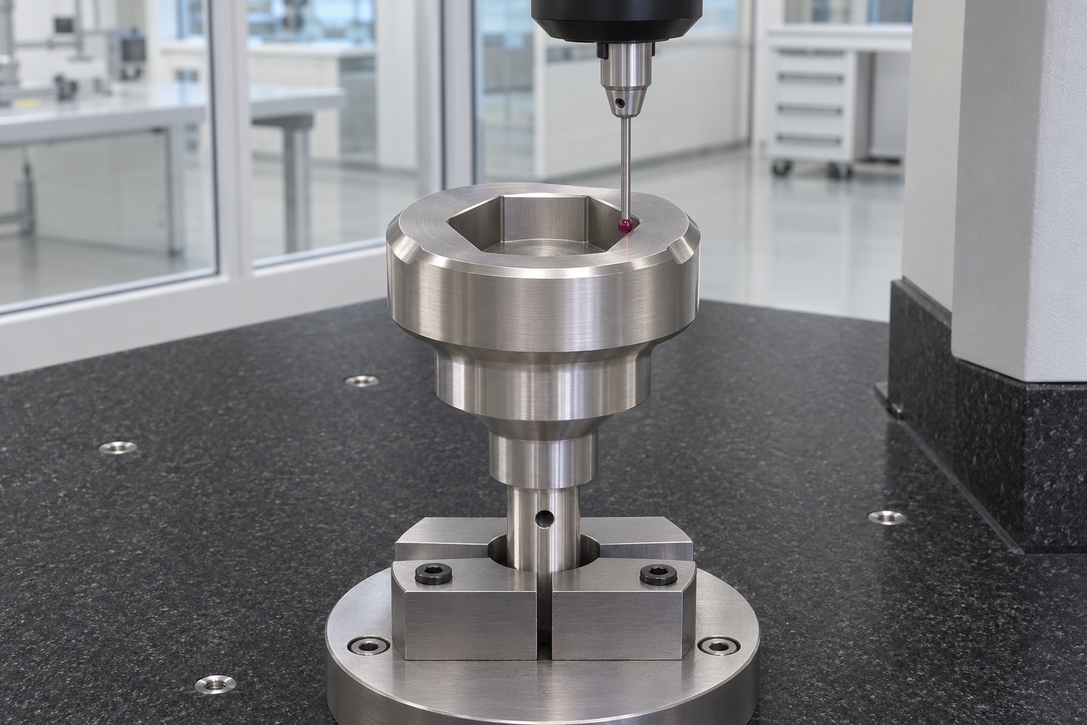
The inspection plan should identify the locating shank, axial shoulder, socket flats and transverse feature in one reproducible datum system. Measure the socket at defined depths, excluding entry and relief regions where appropriate. Record how angular position and cross-hole height are checked. A coordinate or optical method may be considered according to actual access and the required characteristic. An insertion trial is not a substitute for all those relationships. The report should say which features were measured, which were examined by another approved method and which observations belong only to a separate bench fit using identified references.
Use an inert bench comparison for geometry only
A controlled fixture can compare the adapter with identified inert mating references without a cap, vial, specimen or operating capping machine. Record support, orientation and the location of any contact. Do not force a reference to overcome an unexplained obstruction. The observation can reveal a local geometric mismatch under that setup, but it cannot establish capping torque, closure integrity or sample protection. Qualification of a real capping process requires separate approved conditions and evidence. Keep the dry comparison linked to its reference identities so a later check is not presented as equivalent after the fixture or mating piece has changed.
Review discrepancies before corrective machining
If a polygon reference stops early, inspect entry edges, corner relief, depth, reference condition and alignment before changing the pocket. Enlarging all flats may conceal an obstruction while destroying the locating fit. Any correction needs an approved disposition and repeat measurement of affected characteristics. The same principle applies to a pin that does not enter the transverse hole: identify the cause instead of drilling the feature larger by default. Preserve the original observation and distinguish measurement setup, removable burr and incorrect geometry. These are different findings even when they first appear as the same assembly symptom.
Protect the interface and prepare the request
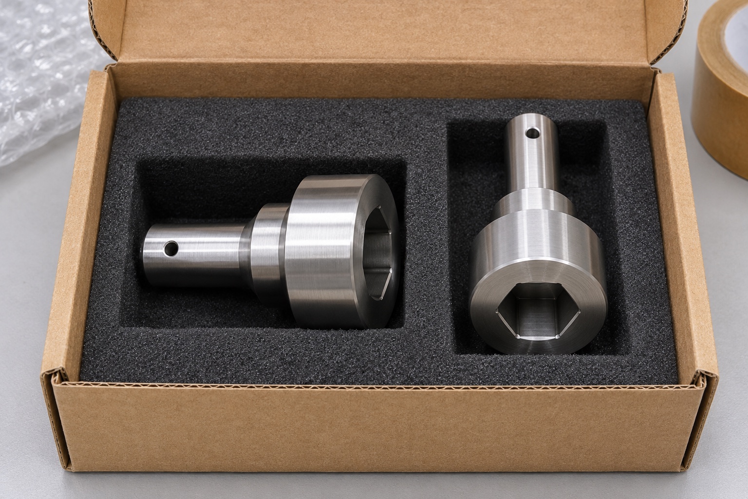
Separate adapters during transport so shanks, shoulders and socket entries do not strike other metal parts. Use protective contacts allowed by the handling specification and maintain revision and material identity with the inspection record. Ordinary packing does not establish sterile delivery. A manufacturing request should include the controlled drawing, material, quantity, final surface state, socket details, datum scheme and required evidence. Resolve corner access and measurement concerns before ordering a batch. Agree how first-article findings will be reviewed. This makes the supplier's contribution verifiable without inventing a closure specification or approval for the complete laboratory capping process.
FAQ
Does the cryovial name qualify low-temperature operation?
No. The name identifies an application context. Exposure conditions and suitability require their own approved specification and evidence.
Does a nominal hexagon define the complete socket?
No. Define useful flats, depth, entry, corner conditions and any angular relationship, with inspection requirements appropriate to the actual interface.
Can milled internal corners be assumed perfectly sharp?
No. Review the cutter radius, permitted relief or another approved process before manufacturing; do not enlarge the whole socket without authorization.
Does a passing pin prove cross-hole position?
No. It checks a local fit condition. Hole height and angular relationship to the locating references need separate evaluation.
Can an inert mating trial prove capping torque?
No. A dry geometric observation does not establish closure performance, specimen protection or qualification of an automated capping process.
What should be checked when a reference stops early?
Check entry edges, corner condition, depth, reference identity and alignment before approving a correction, then repeat affected inspections.

tanghangyun@oemach.com