
Humanoid foot structures experience changing loads during landing, turning and recovery. A material grade alone does not prove that the finished part can carry those loads reliably.
Manufacturing must connect material and heat-treatment condition with the real load path, ankle interfaces, sole faces, weight-reduction pockets and verification before and after approved impact testing.
Typical failure risks and controls
| Risk | Likely cause | Control and evidence |
|---|---|---|
| Ankle bores shift after impact | Incomplete load path or low local stiffness | Use functional datums and compare bore positions before and after testing |
| Sole connection face distorts | Thin pockets plus clamping force | Support load ribs, limit force and measure in the free state |
| Early fatigue despite adequate strength | Stress concentration, tool marks or inconsistent treatment | Control radii, surface integrity and material condition |
Convert impact loads into manufacturing requirements
Identify ankle bores, sole load faces, sensor areas and structural ribs that carry force. Static dimensions alone may not reveal local compliance, edge stress or joint micro-movement under the approved load spectrum.
Specify material together with its condition
High-strength aluminum, alloy steel and other lightweight materials behave differently with stock route, heat treatment and fiber direction. Drawings should define the state, required certification and any hardness or case-depth evidence.
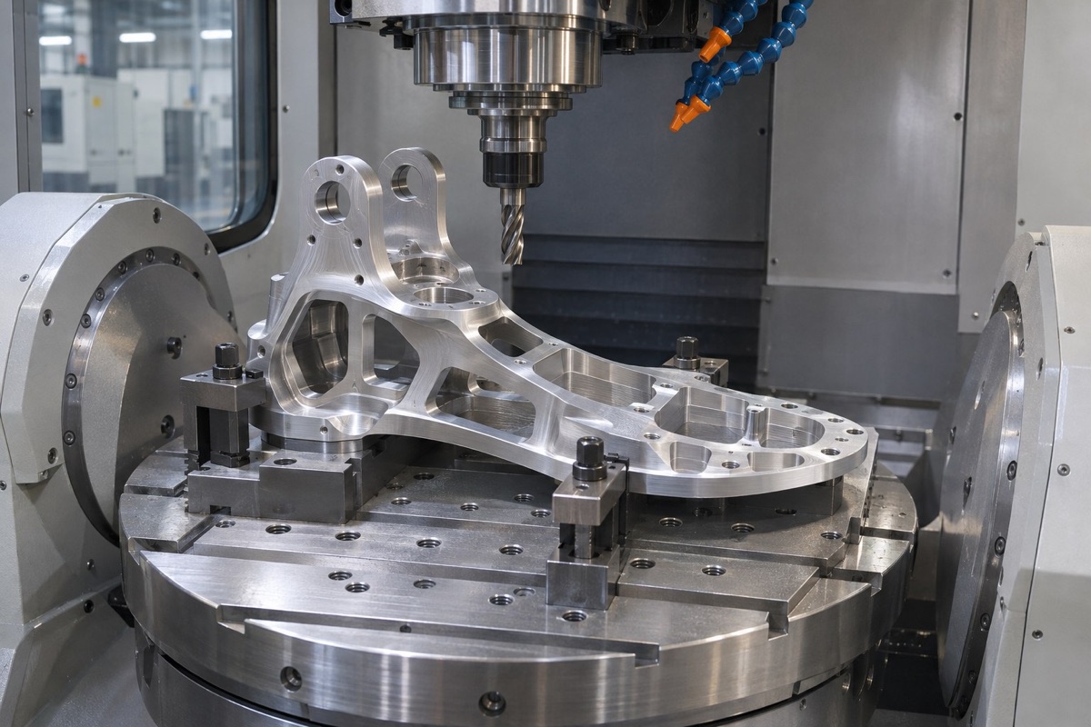
Load-bearing faces, ankle bores and weight-reduction pockets should be planned around stable functional datums.
Use datums that represent the ankle-foot assembly
Build the datum chain from stable load faces and locating features. Preserve that relationship through roughing, heat-treatment checks and finishing, and complete or recheck critical holes after large weight-reduction pockets reduce stiffness.
Control clamping and stock removal
Support primary ribs, avoid forcing flexible regions and remove material in a balanced sequence. Release the part after roughing and record its natural shape before final machining.
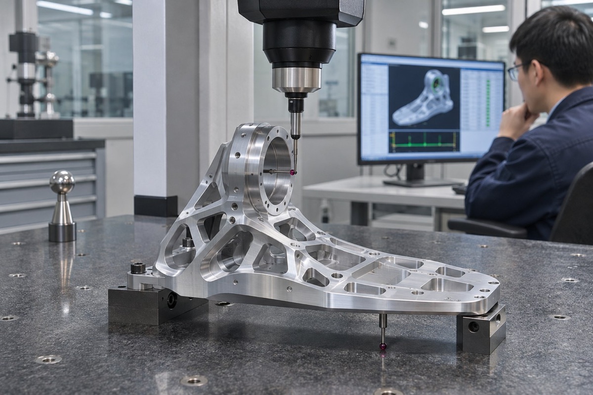
Critical geometry should be rechecked after unclamping and related to the approved impact and fatigue test conditions.
Protect surface integrity and validate the first article
Avoid burrs, burns and severe tool marks at bores, fillets and steps exposed to cyclic load. Link dimensions, material batch, treatment state and inspection conditions to the assembly's impact and durability records.
Summary
Reliable humanoid foot parts require a verified material state, datum planning around the true load path, low-distortion machining and evidence that links part geometry with project-specific impact and fatigue tests.
FAQ
Is a harder foot component always better?
No. Hardness must be balanced with toughness, fatigue behavior, machinability and the actual structure and load case.
Is sole-face flatness enough for acceptance?
No. Its relationship to ankle bores, locating faces and sensor mounts also affects assembly and load transfer.
Can impact parameters from another robot be reused?
Not without validation. Mass, gait, sole compliance and control strategy change the load spectrum.
Ready to get a quote for your CNC machined parts?
Submit your engineering drawings to qiancj@oemach.com. We support prototype sampling and small-batch production with strict tolerance control.