
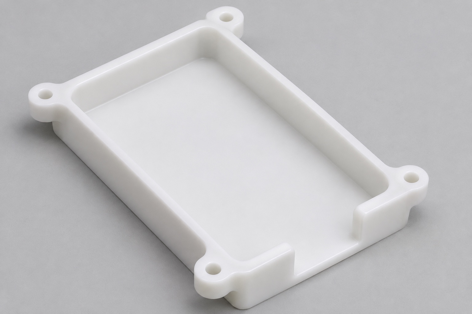
Separate the machined tray from electrical functions
POM-C CNC machining of a portable ECG recorder battery tray concerns a mechanical housing insert, not a complete battery system. A shallow pocket can locate an identified pack envelope while mounting features connect the tray to a separately specified enclosure. This article addresses geometry, manufacturing and inspection of that insert. It does not select a cell chemistry, charging arrangement or electrical insulation system. No claim about recorder safety, battery life or signal quality follows from a correctly machined pocket. The device owner must define the approved pack and operating conditions. Keep the supplier's dimensional evidence distinct from the validation required for an actual medical electrical device.

Define the supported envelope rather than a generic battery
Identify the approved mechanical envelope that the pocket must accommodate. Include protrusions, connector space and any allowed protective layers if they affect the interface. A nominal length and width may not describe rounded corners or local features. Do not measure an unidentified live pack and treat it as the entire design requirement. The drawing should distinguish intended support from clearance, including which surfaces are allowed to contact the pack envelope. If a separate retainer provides restraint, specify its relationship without assuming that every pocket wall is load bearing. This prevents a convenient machining surface from becoming an unintended pressure point in the assembly.
Establish mounting and seating references
Choose the tray face that seats in the enclosure and identify the features that locate it laterally. Relate pocket position and mounting holes to those references. The outer rectangular outline is not automatically the working datum if only selected pads actually contact the housing. State whether acceptance applies in the free state or under a defined mounting condition. A thin floor forced against a fixture can appear different from the same part after release. The inspection method should recover the agreed references without relying on a functioning recorder. Matching the support condition to the requirement is essential before drawing conclusions from a pocket-depth or flatness reading.
Describe the pocket floor and corner condition
Separate overall pocket depth, useful support areas and local relief. A cylindrical milling cutter leaves internal corner radii; compare them with the approved inert pack envelope before choosing the tool route. If clearance relief is necessary, obtain design approval rather than enlarging the entire pocket. Increasing every wall clearance could alter retention or available mounting section. Do not infer a corner requirement from a rendered picture. The drawing and model should identify where contact is intended and where a gap is required. Also review access for later inspection so a nominal depth reading is not taken on a relief or an entry feature by mistake.
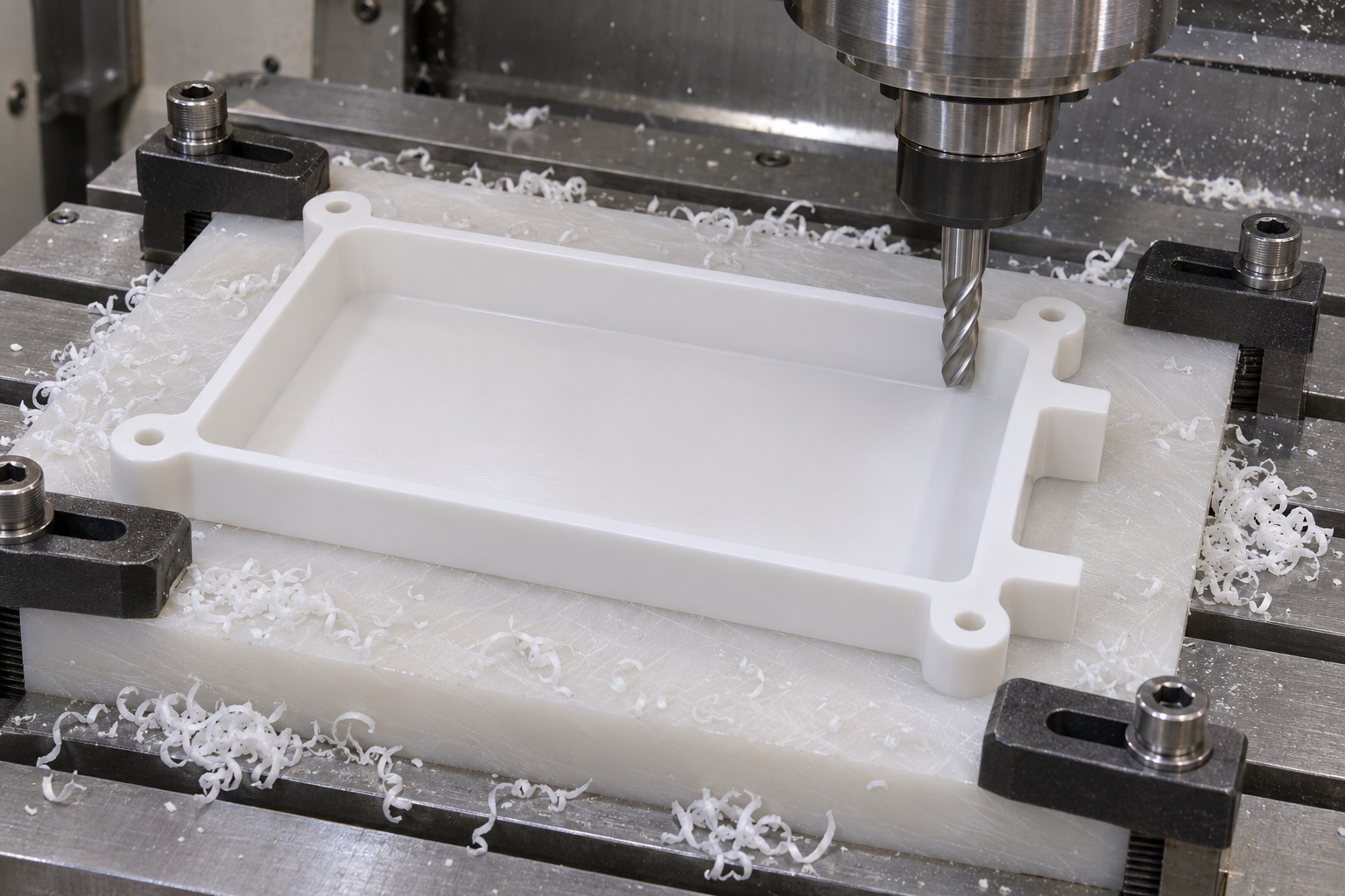
Review end clearance and connector access
An end notch or cable exit needs defined geometry and a relationship to the pocket and enclosure. The space available for an inert connector reference may differ from the simple opening viewed from above. Review the rear envelope, installation direction and nearby fasteners using approved component information. The machining supplier must not invent bend limits or electrical clearance requirements. Those belong to the device definition. The manufacturing package should nevertheless show which regions must remain unobstructed and which edges require a controlled condition. A part that accommodates a rigid mockup under one direction of insertion has not automatically demonstrated suitability for a real cable or battery assembly.
Specify the acetal grade and supply condition
Use the requested POM-C grade and stock form, with any material identification and documentation explicitly stated. POM-C and POM-H are not interchangeable simply because both are called acetal. Neither a material family name nor its color establishes approval for the intended device. Define the condition in which dimensions are accepted and any required storage or conditioning instructions. Do not add a universal heat-treatment recipe to every plastic part. Material behavior and process decisions depend on the actual stock and geometry. If special cleaning is requested, agree its method and acceptance separately rather than implying that a machined white polymer is automatically medically qualified.
Plan pocket removal with remaining support in mind
Milling a broad pocket changes the amount and distribution of material supporting the finished tray. Review floor and wall sections, tool access and how the blank will remain located as material is removed. A route suitable for a thick block may not suit a shallow thin-floor insert. The supplier should select conditions for the actual grade and machine, not copy a generic metal cutting recipe. Identify which references are established first and how they survive later operations. If the tray is turned over to finish its mounting face, the process plan needs a clear transfer method rather than an assumption that the pocket alone provides a reliable new support.
Avoid clamping the part into apparent conformity
Workholding contacts should support approved regions without bending walls or forcing the pocket floor into a preferred shape. Record where clamps act and whether those contacts touch functional surfaces. A measurement taken under substantial constraint may describe the fixture more than the free part. If the drawing requires a mounted condition, reproduce and document that condition instead of choosing arbitrary pressure. Differences between readings should prompt a review of support and contact force before a material or machine is blamed. This is especially important when a broad shallow cavity leaves limited remaining section. A visually flat floor while clamped is not by itself an acceptance result.
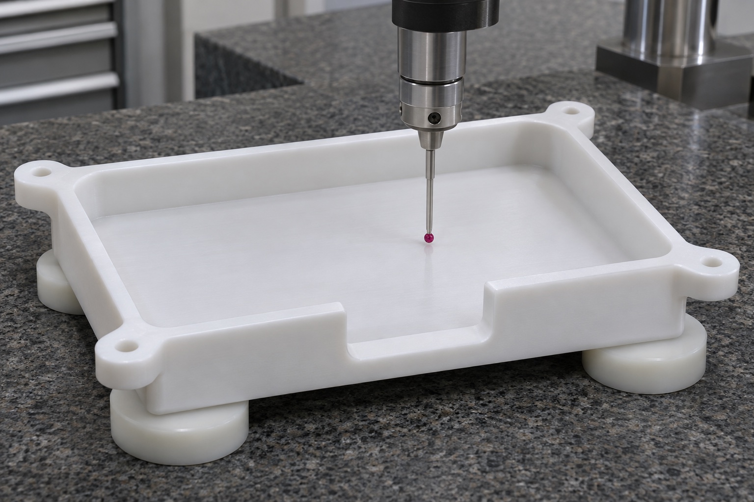
Finish entries without changing support contacts
Remove loose material at the pocket entry, end notch, mounting holes and accessible transitions. Deburring must not round away a specified seating pad or change an end stop. Inspect affected features after a finishing operation capable of altering them. Do not use an insertion trial to push aside a raised edge and accept the pocket automatically. Ordinary chip removal is different from a defined cleanliness requirement and does not establish electrical safety or sterile delivery. Identify any prohibited residues or handling constraints in the purchase requirements. Packaging and cleaning instructions should be compatible with the approved material and final surface condition rather than added as generic promises.
Measure the tray using its defined references
Inspect pocket support geometry, usable depth, end clearance and mounting pattern in the required relationship. A caliper reading across the outside does not confirm the internal envelope or hole position. Select methods that reach the actual support regions without deforming them. A coordinate or optical method may be considered according to access and the characteristic, but the reference scheme still needs definition. Record the drawing revision and material state. No tolerances or measurement values are invented here. Real acceptance depends on approved requirements and evidence from identified parts, with any limitations or unverified features stated rather than concealed by a successful local size check.
Use only identified inert references for a dry comparison
A non-electrical inert envelope can help locate mechanical interference without using cells, charging circuits or a powered recorder. Its shape and revision must be identified. Record insertion direction, support and contact location; do not force it into a pocket that stops unexpectedly. The comparison cannot establish battery restraint under service loads, thermal behavior, electrical isolation or compliance of a medical device. Those are separate evaluations under the device owner's plan. If the reference fits differently after changing orientation, review the permitted assembly direction and the reference geometry before modifying the tray. Keep the original observation available for an approved diagnostic decision.
Protect the tray and prepare the manufacturing request
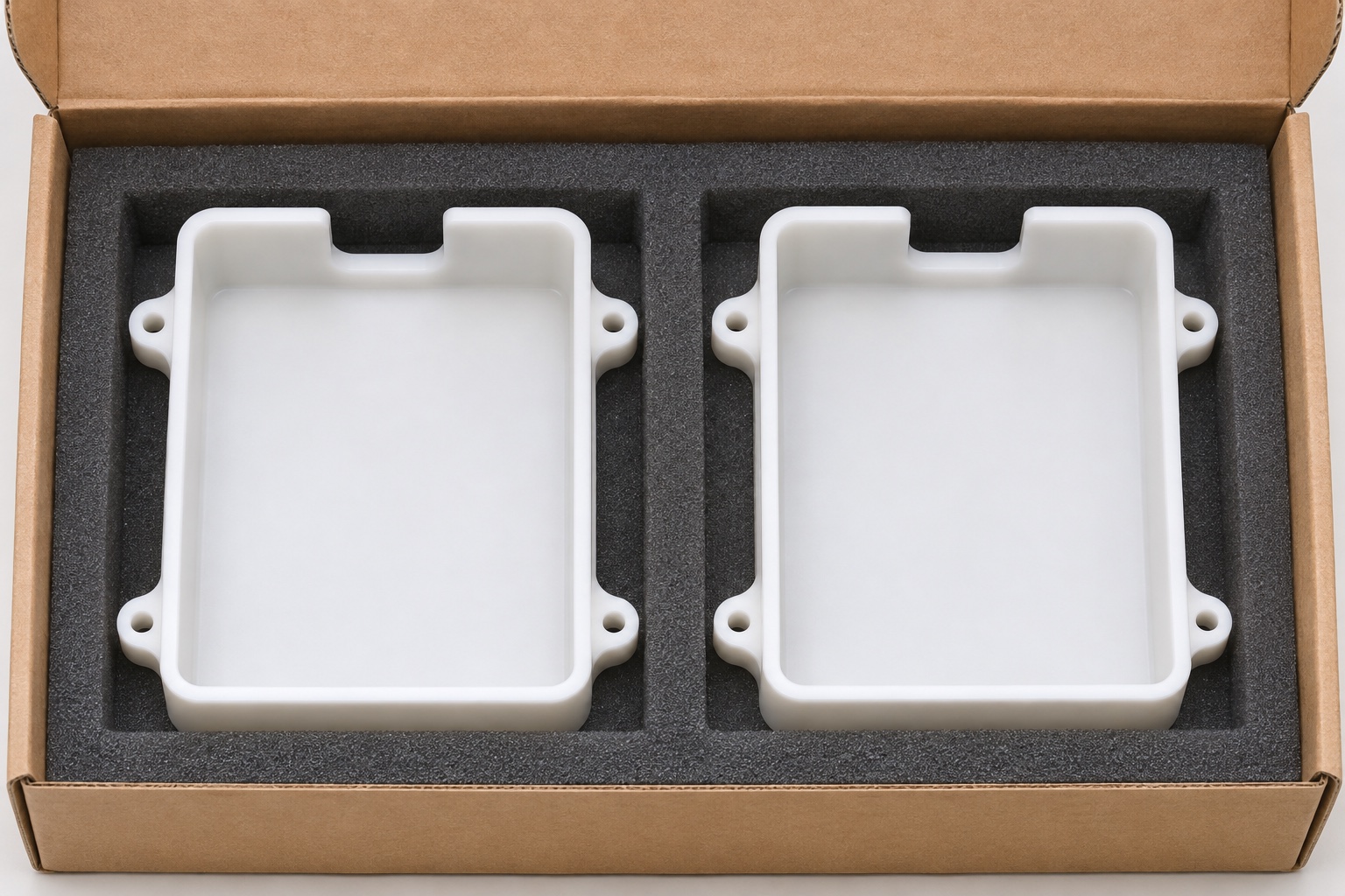
Keep trays separated during transport and support them without flexing the floor or loading thin walls. Prevent packaging fragments from entering the pocket or cable exit. Maintain revision and material identity on the packaging or a permitted exterior region, not on functional contacts. A real RFQ should include consistent model and drawing, grade, quantity, final state, reference scheme, pocket and end-clearance requirements, inspection evidence and protective packaging. Provide the approved inert envelope where it governs fit. This supports a verifiable medical plastic machining scope while leaving battery selection, electrical safety and recorder qualification with the responsible device organization.
FAQ
Does POM-C automatically provide approved electrical insulation?
No. The material name and a machined geometry do not establish an insulation system or device safety. Requirements and verification must come from the responsible medical device design and evaluation process.
Is a nominal battery length sufficient for the pocket?
No. The approved envelope may include corners, protrusions, connector space and protective layers. Identify intended contacts and clearance regions rather than treating every wall as a restraint surface.
Can pocket corners be assumed perfectly sharp after milling?
No. A cylindrical cutter leaves radii. Review matching geometry and any approved relief before production; do not enlarge all pocket walls to solve an unexplained corner interference.
Why distinguish free-state and mounted inspection?
Support and clamping can change the observed shape of a thin-floor tray. Measure in the specified condition and document it, instead of comparing constrained and free readings as though they were equivalent.
Can a live battery be used as the only fit reference?
This guide limits the comparison to identified non-electrical inert references. A geometry check does not require cells, power or charging and cannot establish the safety of a real battery assembly.
What should be supplied with the tray RFQ?
Provide controlled files, POM-C grade, quantity, final condition, mounting references, pocket and access geometry, inspection requirements and packaging instructions, together with the approved mechanical envelope where relevant.

tanghangyun@oemach.com