
Passing mechanical dimensions does not guarantee a reproducible optical path. Beam-splitter and reference-mirror mounts must translate optical axes and mirror normals into a traceable mechanical datum system.
First-article approval should connect CMM results with optical alignment, available adjustment travel and repeated disassembly tests under controlled cleaning and locking conditions.
Common failure modes and controls
| Failure mode | Control | Evidence |
|---|---|---|
| Unstable interference signal | Unify optical and mechanical datums; control contact faces | Pose, temperature and signal records |
| Dimensions pass but alignment runs out of travel | Define axis, rotation center and usable adjustment range | Travel margin and alignment report |
| Zero changes after reassembly | Use repeatable locating features and fixed cleaning/locking steps | Repeated mechanical and optical zero data |
Translate the optical path into datums
Define the effective mirror surface, beam height, mounting face, locating holes and adjustment axes in one coordinate system. A datum chosen only for easy fixturing may leave every dimension acceptable while forcing excessive compensation during alignment.
Control mirror seats without stressing optics
Steps, retaining rings, adhesive layers or flexures must set pose without distorting the optic. Contact width, edge breaks and coating thickness alter the final location, so drawings should distinguish optical contact surfaces from housing and fastening features.
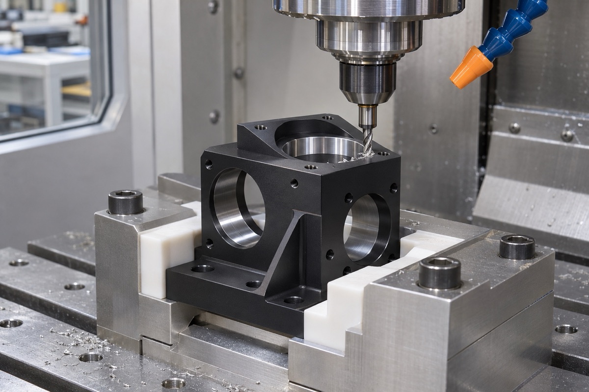
Mirror seats, locating holes and adjustment axes should be machined around the same optical reference.
Reserve adjustment travel and thermal margin
Pitch, yaw and axial adjustment compensate only a limited error. Verify bidirectional margin around nominal zero and assess material combinations, coatings and nearby heat sources over the operating temperature range. A mount that aligns only at the end of travel is not robust.
Combine dimensional and optical evidence
CMM data proves faces, holes and datums; optical methods prove mirror normal and returning beam. Repeat assembly with a fixed cleaning and locking sequence to separate locating error from contamination, mirror quality, air disturbance or laser-source variation.
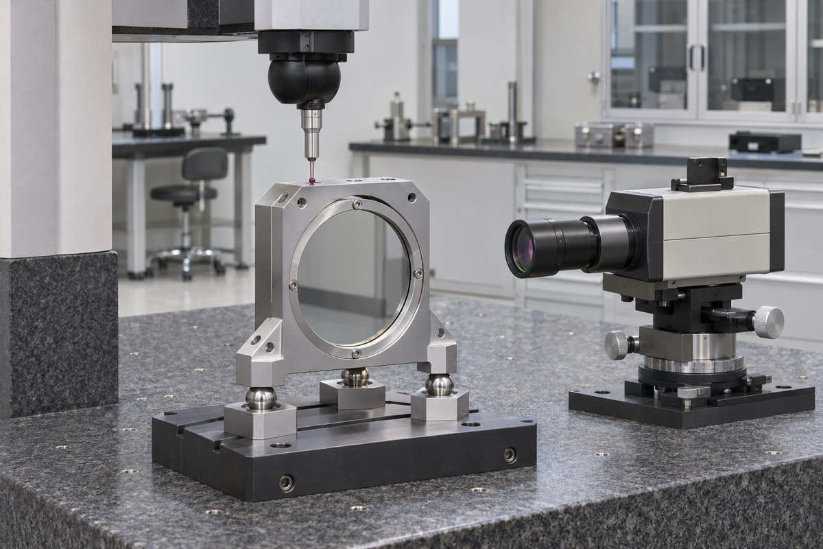
Repeated assembly connects measured geometry with the reproducibility of the interferometer signal.
Summary
Interferometer mounts need a shared optical-mechanical datum chain, stable mirror contact, usable adjustment margin and mechanical plus optical verification.
FAQ
Is a blacker mount always better?
No. Stray-light control must also satisfy dimensional, adhesion, cleanliness and environmental requirements.
Can adjustment screws justify looser machining?
Not automatically. Travel is limited and large offsets reduce stiffness and repeatability.
Can a CMM report replace optical alignment?
No. The two methods verify different but complementary requirements.
Ready to get a quote for your CNC machined parts?
Submit your engineering drawings to qiancj@oemach.com. We support prototype sampling and small-batch production with strict tolerance control.