
A heat sink is both a thermal path and a precision mounting structure. Fin count alone cannot prove performance when contact geometry, fastening and temperature gradients can move an optical datum.
Acceptance should combine room-temperature geometry with the assembled interface, temperature distribution and movement of critical optical references across the defined operating range.
Thermal-part risks and controls
| Risk | Control | Evidence |
|---|---|---|
| High interface temperature difference | Control face form, interface material and tightening | Flatness, contact, torque and temperature rise |
| Base warps after fin milling | Separate roughing and finishing; balance removal | Free-state base and fin-shape data |
| Optical path drifts despite dimensional pass | Run thermal-structural verification under operating power | Temperature and datum-displacement curves |
Map heat sources and sensitive datums
Detectors, lasers, drivers and motors create different heat patterns. Define the path from each device through the structure to air, liquid or enclosure, and identify nearby mirrors, focal planes and calibration references. Minimizing one local temperature can still create a harmful gradient across the optics.
Make the contact face functional
Warp, burrs and uneven tightening reduce real contact area and can tilt the device. Flatness, roughness and mounting-hole position should match the interface material and assembly plan; a visually mirror-like face is not a substitute for the required form and contact condition.
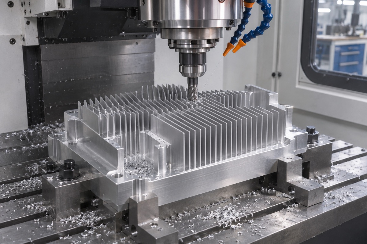
Tool load, chip evacuation and base distortion must be controlled together.
Machine thin fins without moving the base
Tall thin fins are sensitive to lateral tool force, heat and chip recutting. Use sharp tooling, short overhang, zoned or alternating paths and thermal stabilization between roughing and finishing. Inspect thickness, spacing, root condition and the complete base, not a few isolated fins.
Validate the assembled thermal state
Coatings and interface layers belong in the dimensional chain. Assemble the first article with defined fasteners, torque and sequence, then record environment, power, sensor locations, stabilization criterion and critical datum movement. Liquid-cooled parts also need separate cleanliness, flow and leak verification.
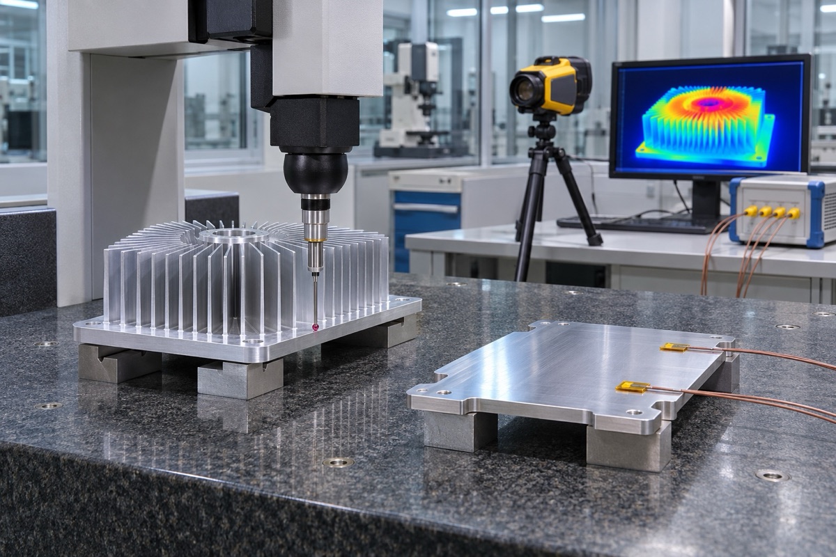
Contact-face metrology and thermal testing jointly evaluate the finished structure.
Summary
Optical heat sinks require controlled interfaces, low-distortion fin machining and thermal tests that connect temperature distribution with optical datum stability.
FAQ
Are more and thinner fins always better?
No. Flow, root conduction, stiffness, machinability and cleaning also matter.
Must the contact face be mirror finished?
No. Form and surface condition must match the interface and fastening design.
Does room-temperature CMM approval prove thermal stability?
No. Stability requires testing under defined power, environment and time.
Ready to get a quote for your CNC machined parts?
Submit your engineering drawings to qiancj@oemach.com. We support prototype sampling and small-batch production with strict tolerance control.