
A precise individual bore does not make a precise scan head. Bearing bores, end faces, mirrors and feedback sensors must remain stable around a common axis and coordinate system.
Mechanical inspection should be linked with assembly eccentricity, thermal drift and optical calibration; software cannot correct looseness, friction or changing geometry.
Scanner errors and manufacturing controls
| Symptom | Control | Evidence |
|---|---|---|
| Scale or orthogonality error | Control two-axis geometry and calibrate with a standard pattern | Angles, coefficients and scan error |
| Zero drifts with temperature | Control thermal interface and sensor location | Temperature, zero and stabilization time |
| Noise at high speed | Check bore alignment, mirror balance and mount stiffness | Geometry, assembly and response data |
Start with one scanner coordinate system
The two motor axes, mirror centers and system optical axis jointly define scan geometry. Drawings should state mounting faces, center heights and direction datums rather than letting each part be best-fitted in its own local coordinates.
Finish bearing bores and faces together
Roundness, coaxiality and face squareness affect friction, runout and dynamic behavior. Finish critical features in a stable setup, limit clamping distortion and inspect bore form at several sections as well as its relationship to the end face.
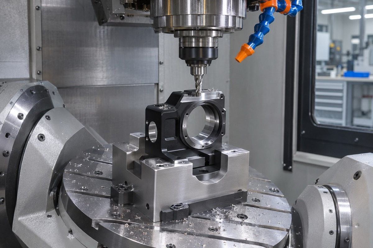
Critical bores, faces and hole patterns should be finished around a shared motor axis.
Control mirror mass center and feedback zero
Seat geometry, adhesive or clip thickness can move the mirror from the rotation axis and create imbalance. The feedback-sensor mount must also recover the same electrical zero after replacement. Use repeatable locating features and verify assembly, cure, preload and balance conditions.
Connect static metrology with dynamic results
Record contact-face condition, tightening, operating power, temperature and stabilization time. CMM, roundness and optical alignment data establish geometry; standard scan patterns establish system behavior. Project limits depend on field size, focal length, speed and application.
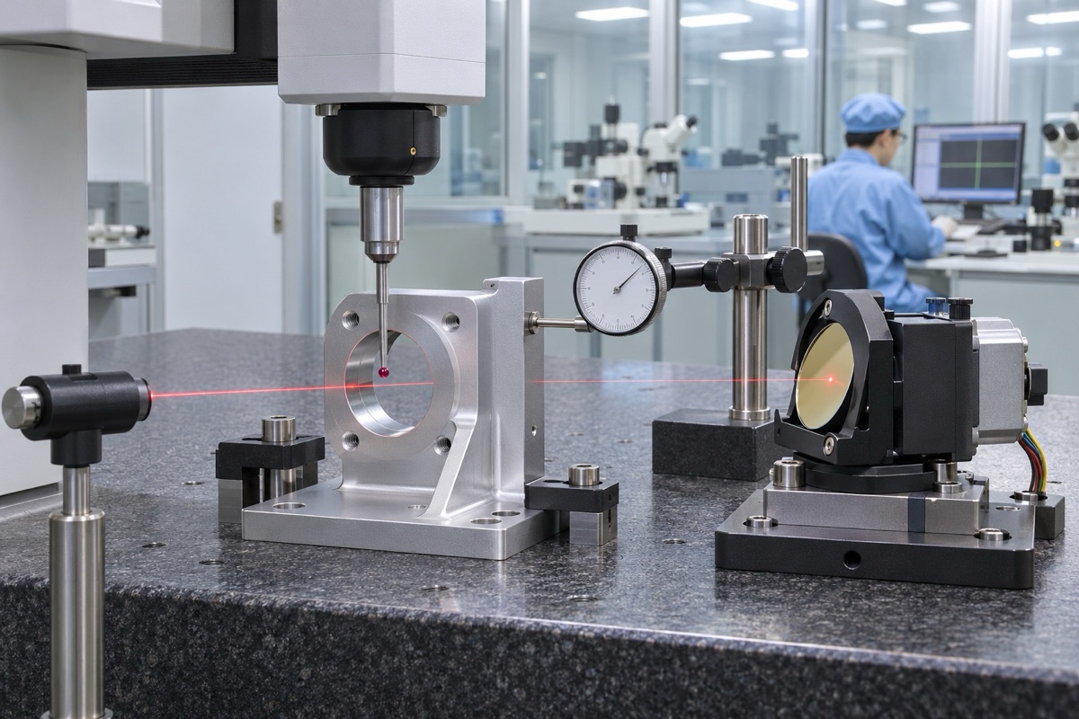
Static metrology must be connected with optical alignment and system calibration.
Summary
Stable galvo parts are produced from a shared axis system, controlled bore and mirror geometry, repeatable sensor location and validation that connects mechanics with scan calibration.
FAQ
Why can an in-tolerance bore still run hot?
Bore form, coaxiality, face relation or bearing preload may still be wrong.
Can software calibrate every scan error?
No. It cannot remove looseness, thermal drift, friction or dynamic vibration.
Can the two-axis angle be set only during assembly?
Not reliably if the part datums cannot reproduce that angle.
Ready to get a quote for your CNC machined parts?
Submit your engineering drawings to qiancj@oemach.com. We support prototype sampling and small-batch production with strict tolerance control.