
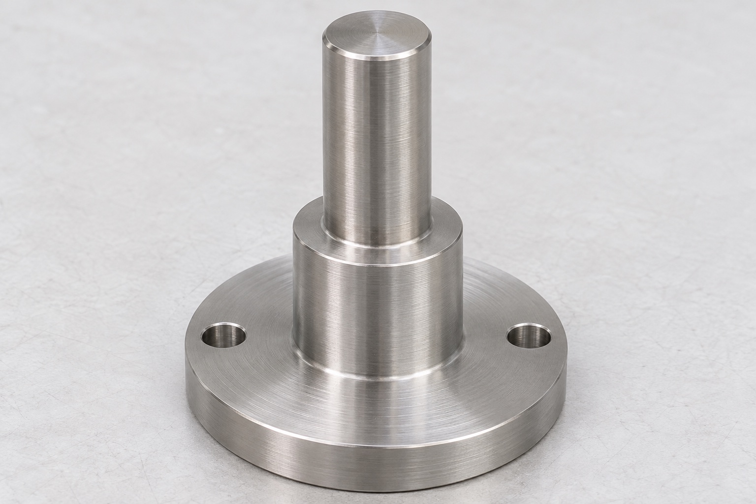
Start with a defined mechanical guide
316L CNC turning for a blood analyzer cuvette lift guide post addresses a mechanical part made to an approved drawing. The representative geometry is a stepped cylindrical shaft with an annular shoulder and a flat mounting flange. The guide surface constrains a separately defined mating component; it does not itself demonstrate accurate cuvette movement or an analyzer result. This article explains manufacturing, datum selection and inspection questions. It does not approve a replacement for a commercial analyzer or specify operating adjustments. The device designer must supply the actual guide interface, acceptance limits and final condition before a supplier can quote a verifiable custom component.

Separate useful guide length from the overall shaft
Mark the shaft region that provides guidance and distinguish it from entry edges, relieved areas and nonfunctional extensions. Overall shaft length does not establish how much cylindrical surface supports the mating reference. The approved drawing should identify the start and end of the useful region and any excluded transition. A size measurement near one end cannot verify the entire guide. Specify the relevant size and form requirements without assuming that every turned surface has the same role. This distinction helps procurement request appropriate evidence instead of comparing suppliers on a single diameter while leaving the important length undefined.
Identify the working axis and mounting datums
Decide which surface defines the working axis and how it is related to the flange or other mounting references. A supplier should not automatically use the stock axis or an accessible exterior edge as the acceptance reference. If the guide cylinder establishes location, the inspection plan must recover that reference consistently. The axis relationship to the mounting face is separate from its diameter. Where approved mating geometry governs position, include it with the enquiry. A clear datum scheme connects the turning setup, later mounting operations and final inspection, reducing the chance that each stage evaluates a different interpretation of the same guide post.
Define shoulder contact and transition clearance
An annular shoulder needs a position, a useful contact band and a defined relationship to the guide axis. Its outside outline alone does not describe an axial seat. Review the allowed corner radius or relief where the shaft changes diameter and compare it with the approved mating corner. A transition that contacts first can prevent seating on the intended band. Keep overall length, shoulder location and flange thickness as distinct characteristics where they serve different functions. Do not remove a shoulder edge simply to make one reference fit; the useful contact and any permissible edge treatment belong in the controlled interface definition.
Specify material, surface and acceptance state
The request should state the required 316L specification, stock form and material-document scope. Any approved surface treatment, marking or special cleaning requirement should identify the dimensions and surface conditions that apply afterward. A bright shaft does not establish alloy identity, wear performance, biological evaluation or cleaning validation. If surface texture matters to the guide interface, define it rather than asking for a generally polished appearance. The manufacturing record should connect the material, drawing revision and final state. Measurements from before a later operation must not silently become the evidence for acceptance of the finished component after that operation.
Review a turning route around the functional cylinder
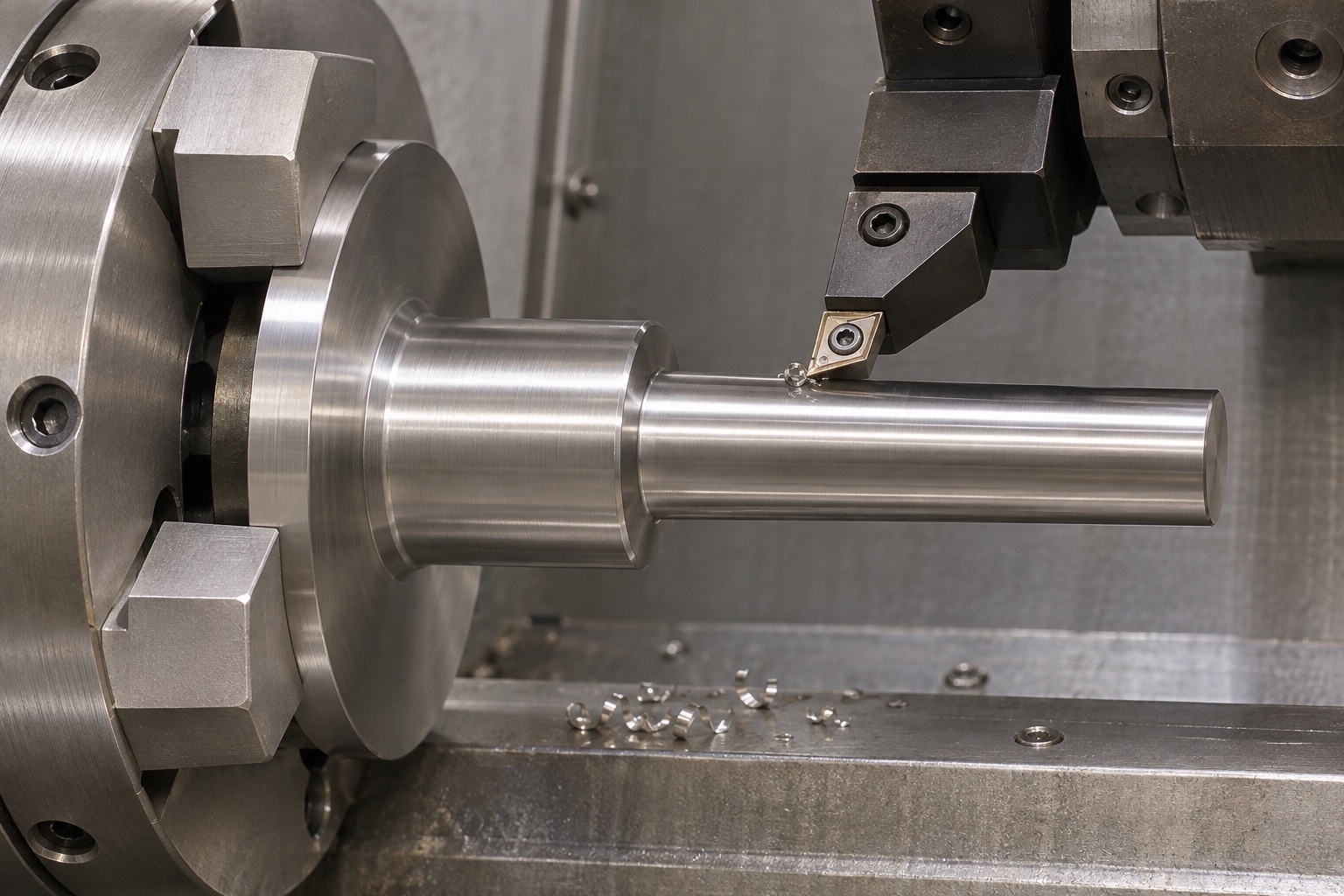
The process review considers stock support, access to the shoulder and flange, and which relationships can be generated together. The appropriate route depends on actual dimensions and equipment; no universal speed, feed or cycle time is proposed. Identify operations that leave the useful guide surface vulnerable to marks or distortion. Producing several features in one setup can simplify reference transfer, but does not replace inspection. If the post must be reversed, explain how the functional reference will be recovered. A process plan should show how the final part remains measurable, not only how the tool can reach the desired shape.
Protect the guide during mounting-feature work
Flange holes or other approved mounting details may require secondary milling or drilling. Their location should follow the defined reference system rather than a convenient unrecorded fixture edge. Review how the post is supported during these operations and how the finished guide cylinder is protected from jaw marks. Do not use excessive clamping to produce a favourable measurement. If the flange is checked in a specified mounted condition, keep that condition distinct from ordinary machining workholding. Recheck affected features after operations that could alter a completed reference. This is particularly important when an apparently minor mounting operation changes how the component sits during inspection.
Preserve functional surfaces during edge finishing
Define the edge condition at the guide entry, shoulder, flange perimeter and mounting holes. Removing raised material should not shorten the useful guide region or eliminate an intended shoulder band. Identify checks that must be repeated after finishing. Ordinary chip removal should also include accessible recesses and holes so loose material is not carried into a geometric comparison. Any special cleanliness requirement needs an approved process and evidence separate from ordinary handling. This guide does not claim sterile supply or validated disinfection. Protective packaging can preserve a machined surface without proving that the complete analyzer has been qualified for its intended use.
Match each inspection method to a characteristic
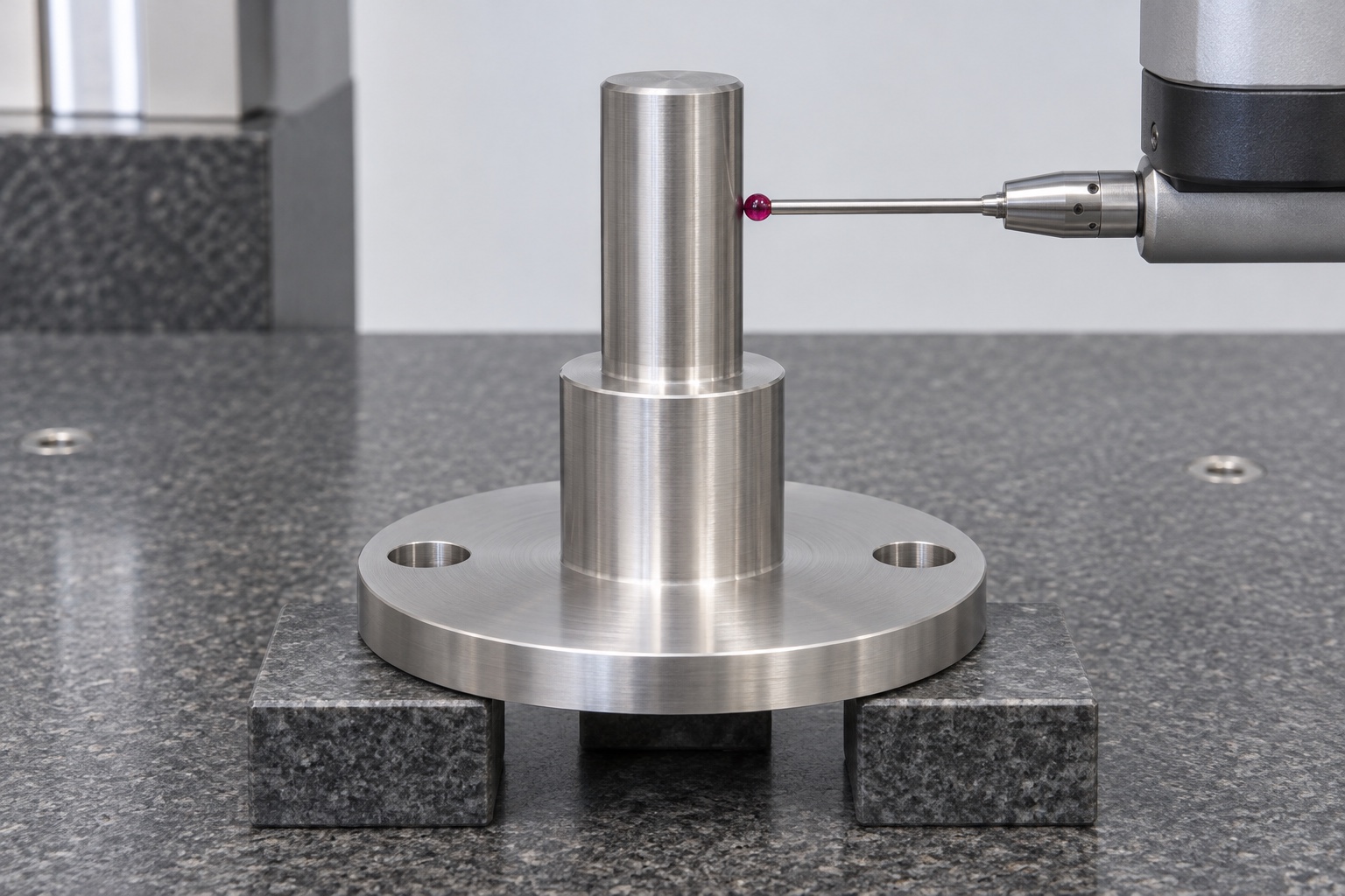
An inspection matrix should distinguish guide size, form over the useful length, shoulder position, face relationships and mounting-pattern location. A local micrometer reading provides a different observation from an assessment of axis orientation. Coordinate, optical or other approved methods require a defined reference scheme and suitable access. State the part condition and instrument identity with actual results. The enquiry should resolve any inaccessible feature before production. This article invents no tolerances, measured values or conformity results. A real report needs approved limits and evidence from identified manufactured parts, not a general statement that CNC turning is precise.
Use an inert sliding reference only within its scope
An identified inert sleeve or approved guide reference can help observe entry and contact without assembling or operating a blood analyzer. Record the reference geometry, support and direction of movement. Do not force it past an unexplained obstruction. A limited sliding observation cannot establish friction under service conditions, wear life, drive-force margin, cuvette positioning or assay accuracy. Those questions require separate approved requirements and evaluation. Keep the reference identity with the record so that replacing the sleeve does not silently change a comparison. Report the actual geometric observation rather than describing one convenient fit as proof of a qualified analyzer mechanism.
Investigate a tight region before changing the diameter
If a reference moves along part of the post but stops elsewhere, review the guide-region definition, local edge conditions, reference alignment, support and the specified part state. Reducing the whole shaft diameter may hide a local issue while changing the intended fit. Preserve the original observation before authorized correction. Separate a manufactured deviation from an incomplete interface definition; the former requires disposition, while the latter requires clarification or revision. Reinspect affected characteristics after approved work. Use the recorded reference and condition when comparing results so a change of fixture or sleeve is not mistaken for an improvement in the same component.
Prepare a complete enquiry and transport plan
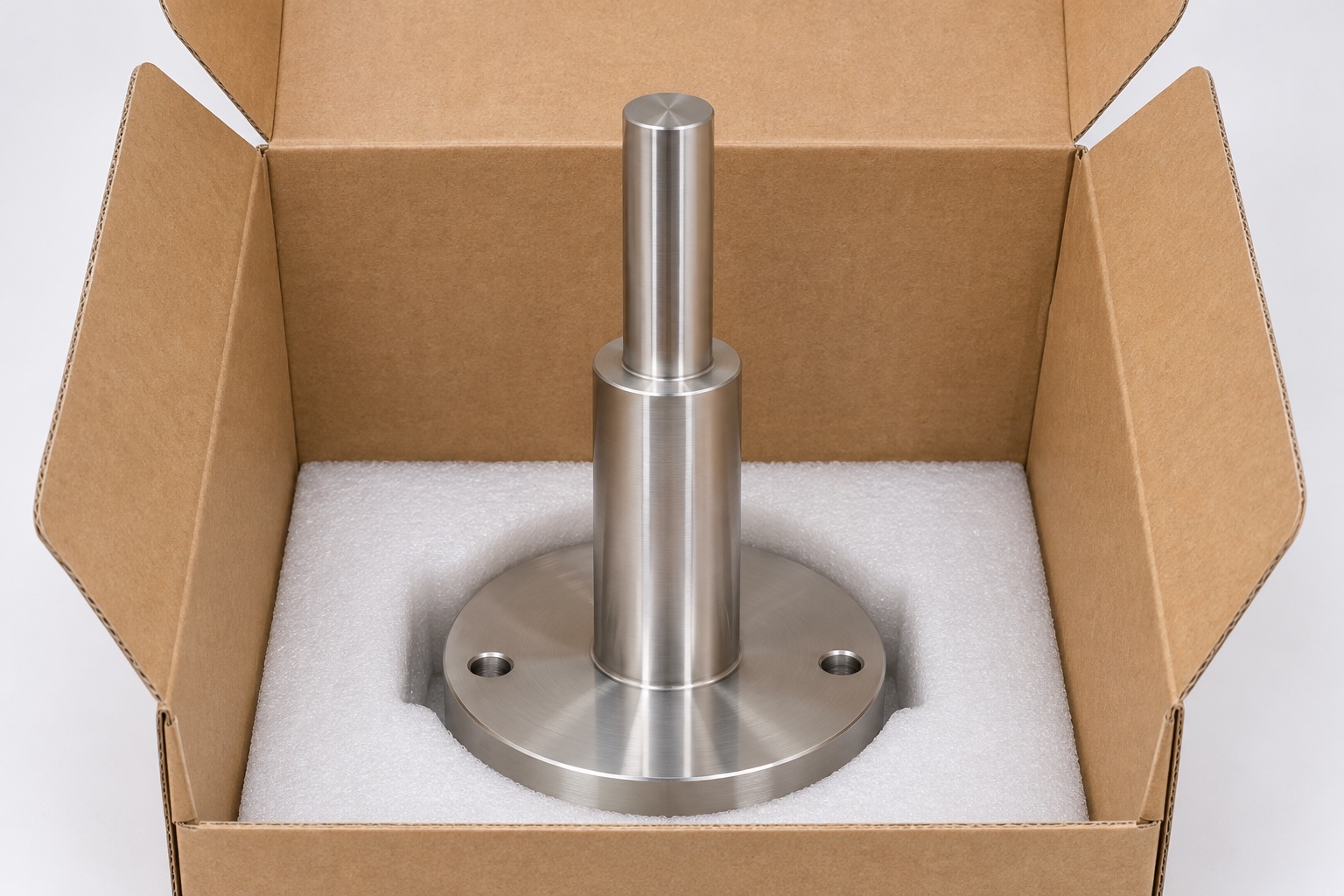
For a useful RFQ, supply approved model and drawing, revision, 316L specification, quantity, guide length and size requirements, shoulder contact, mounting datums, final finish, inspection scope and packaging instructions. Add approved mating geometry where it controls contact. Separate guide posts so cylindrical surfaces and shoulder faces cannot strike other metal parts. Supports should avoid marking the guide or concentrating load on a delicate flange edge. Keep identity and inspection evidence associated with the parts without covering useful surfaces. This gives a medical precision machining supplier a defined component to quote while leaving analyzer operation and performance with the responsible device organization.
FAQ
Does overall shaft length define the useful guide region?
No. The working guide length, entry features and reliefs should be identified separately. An overall dimension does not say which cylinder region must provide controlled guidance.
Does a correct local diameter establish alignment to the flange?
No. Size and geometric relationships are different characteristics. Recover the approved datums and verify the required axis and face relationships separately.
Why specify the shoulder corner condition?
The transition may contact a mating corner before the intended annular seat. Define the allowed radius or relief and the useful contact band before manufacturing.
Can a smooth sliding trial prove analyzer accuracy?
No. It records limited geometric contact, not drive-force margin, wear life, cuvette positioning or the analytical performance of a complete instrument.
Should a tight region be corrected by reducing the entire shaft?
Not without diagnosis and authorization. Review edges, guide length, alignment, support and the mating reference first, then reinspect after any approved correction.
What information makes quotations comparable?
Provide controlled files, material, quantity, functional guide and shoulder definitions, mounting references, final state, inspection evidence and protective packaging requirements.

tanghangyun@oemach.com