
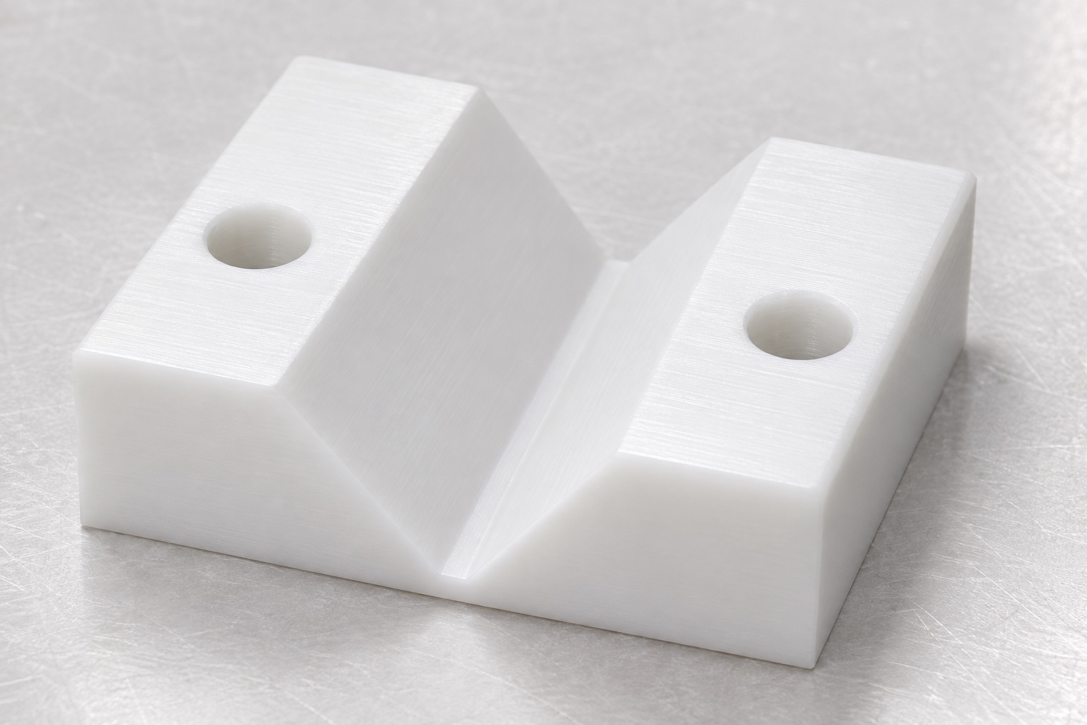
Define the support without implying optical qualification
POM-C CNC machining for a lensmeter frame support shoe concerns a specified mechanical part. The representative component is a rectangular acetal block with an open longitudinal V-groove and two mounting holes outside the contact region. Its role is to provide defined support for an approved frame reference, not to demonstrate optical accuracy. This article addresses machining and dimensional inspection. It does not prescribe lens testing, device adjustment or clinical use. A supplier needs the controlled contact geometry and acceptance requirements rather than an instruction that a spectacle frame should simply sit correctly. Compatibility with a commercial lensmeter cannot be inferred from the application name.

Distinguish the working faces from the groove root
The two inclined faces and the root region can serve different purposes. Identify whether contact is intended on both faces and whether clearance is required at the root. A groove that appears deep enough may still contact a mating edge in the wrong region. Define the useful bands, their limits and the permitted transition condition. The supplier should not infer an ideal sharp internal vertex from a model view. Tool geometry and access must be reviewed before production. Keeping working faces separate from reliefs prevents a convenient depth measurement from being mistaken for proof that the intended support contacts have been achieved.
Specify orientation as well as groove size
Groove angle, position, usable length and orientation to the mounting references are distinct characteristics. A width reading at one height does not independently establish the angle or complete profile. Identify the section and reference system used for inspection, including any regions excluded by edge treatment. If an approved frame reference governs contact, supply its relevant geometry without asking the machinist to select a frame shape. The drawing should distinguish centring, clearance and support requirements. This allows suppliers to price the actual interface rather than produce different V shapes that happen to accept one unidentified sample during a quick trial.
Relate mounting holes to the contact region
The base face and mounting pattern locate the shoe in its surrounding structure. Their relationship to the V-groove should follow the controlled datum scheme. A fastener passing through a hole does not verify the complete pattern or the contact-face orientation. Define useful seating regions and any permitted fastener recesses separately. The intended mounting hardware and inspection state should be specified where they influence acceptance. Do not use arbitrary tightening to make a polymer block sit in a preferred shape. If the surrounding mount determines location, include its approved interface rather than leaving the supplier to invent a fixture that conceals an unresolved design relationship.
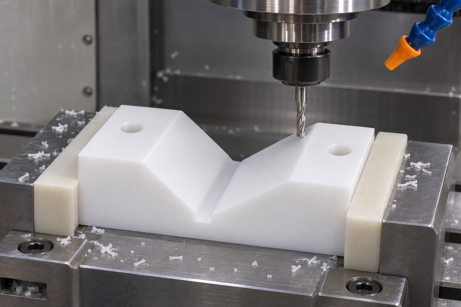
Confirm the POM-C product and final condition
State the approved material grade, stock form, colour and documentation requirements. A generic acetal designation does not establish that every stock product is equivalent. Review the material information for the specified product and keep its identity associated with the part revision. Do not infer optical compatibility, chemical resistance to an unspecified cleaner or device approval from a white appearance. Any conditioning or special handling requirement should have a controlled instruction. Acceptance must refer to the specified final state, so readings from an intermediate operation or an undocumented material condition are not compared as if they described the same finished component.
Plan the groove around accessible references
The machining review should consider how to create the base, groove faces and holes while maintaining support and access. The actual sequence depends on dimensions, stock and equipment; this guide does not prescribe universal feeds, speeds or a particular cutter. Identify which relationships can be generated together and which require transfer. The useful face lengths must remain accessible to inspection after the chosen process. A route selected only for fast tool access may leave an undefined root condition or an inaccessible contact band. Resolve those issues before production rather than adding reliefs or changing the contact profile at the machine without approval.
Keep workholding from defining the accepted shape
Review contact area and support beneath the base before selecting clamps or jaws. A constrained polymer component may not present the same geometry after release. Machining workholding and final inspection support should therefore have distinct documented purposes. If a specified mounted condition is required, reproduce its approved details rather than using whatever screw force makes a reference appear seated. When observations differ, review support, reference recovery and material condition before removing additional material. The objective is a reproducible part against controlled requirements, not a passing trial created by a fixture that deforms the shoe or obscures the relevant contact region.
Finish edges while preserving support bands
Groove entries, root access, mounting holes and external edges need an agreed finishing method. Removing raised material must not erase a useful contact band or change the intended groove length. Identify affected characteristics that require rechecking afterward. Loose chips should be removed before a reference trial so they are not interpreted as a profile problem. Any marking should avoid working contacts. Ordinary chip removal and protective handling do not establish validated medical cleaning or sterile delivery. A clean-looking acetal component also does not prove that it will avoid marking every possible spectacle frame; actual contact and device requirements must be separately defined and evaluated.
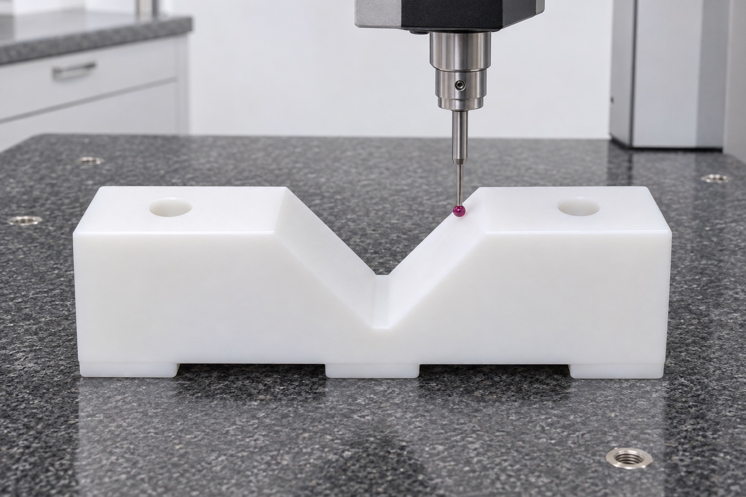
Choose profile and mounting measurements deliberately
The inspection plan should separate groove profile, face orientation, useful length, root clearance, base seating and mounting-pattern location. Optical, coordinate or contact methods still require a defined reference scheme and suitable access. An apparent match in one section does not automatically establish the profile along the full support length. Record which region was measured and how the component was supported. A real report must identify revision, material state, instrument and actual results against approved limits. This article publishes no invented angles, tolerances or measurement outcomes. A generic claim of precision should not replace characteristic-based evidence for the relevant mechanical interface.
Limit the inert reference trial to contact observations
An identified inert frame-shaped reference can help observe contact and clearance without using or adjusting a lensmeter. Record its geometry, orientation and support. Do not force it into the groove or treat rocking under arbitrary pressure as a normal acceptance method. A contact trial does not establish optical alignment, lens power accuracy, frame compatibility across a product range or clinical suitability. Those questions require separate device requirements and evaluation. Keep reference identity with the observation so that a different shape is not silently substituted during later comparisons. The supplier should report the actual contact region and the limits of what the trial can demonstrate.
Diagnose uneven seating before widening the groove
If a reference contacts only one face or rocks unexpectedly, review the section definition, root clearance, entry edges, base support and reference alignment. Widening the entire groove may hide local interference while altering the intended support geometry. Preserve the initial observation and determine whether the issue is a manufacturing deviation or an incomplete interface definition. The required authorization is different in each case. Following any approved correction, inspect affected characteristics again using the specified state and a recorded reference. A later fit under changed support should not be presented as an equivalent before-and-after result without explaining what actually changed.
Quote and protect a specified frame support
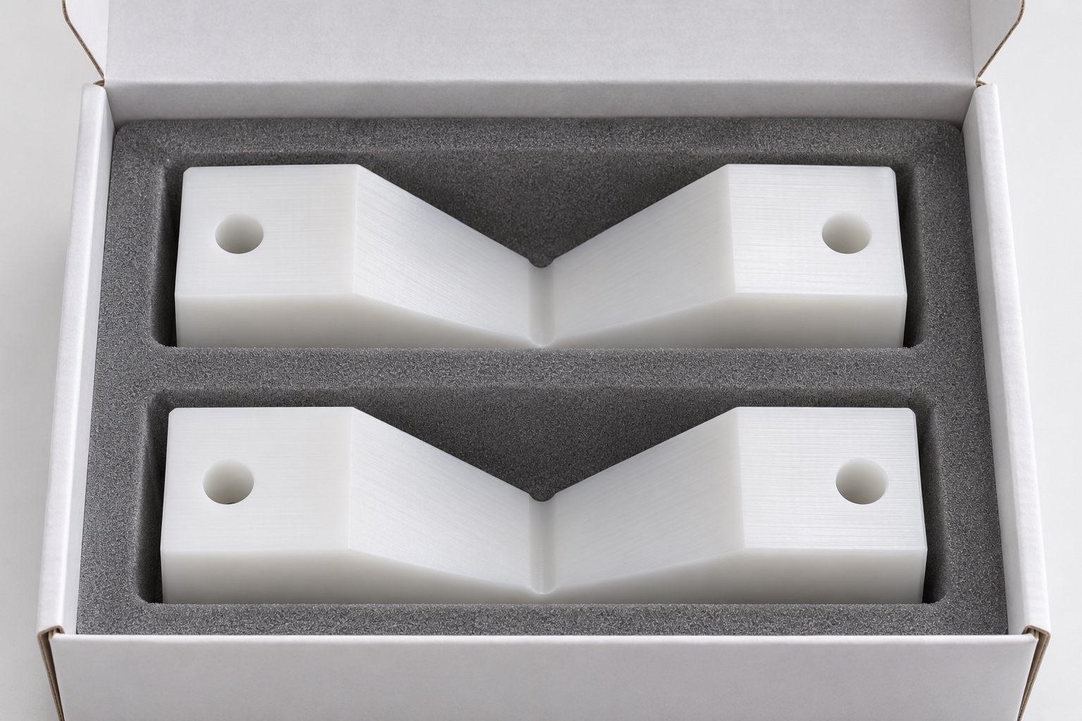
An effective RFQ includes approved files and revision, POM-C grade, quantity, final state, useful groove faces, root condition, mounting datums, mating reference, inspection evidence and packaging requirements. Identify features whose acceptance applies after any approved operation. Separate shoes so groove edges and contact faces do not rub against neighbouring parts during transport. Packing should support the base without inserting a wedge into the V-groove or leaving fragments at the root. Keep identity and inspection records associated with the parts. This creates a verifiable medical plastic machining enquiry while leaving lensmeter qualification and measurement performance with the responsible device organization.
FAQ
Does a groove width reading establish the full V profile?
No. Angle, section height, face orientation and useful length may need separate definition and checks. One width cannot establish every contact relationship.
Must the groove root be perfectly sharp?
Not automatically. Define the allowed root condition and the intended working faces. Tool access and any permitted relief should be reviewed against approved mating geometry.
Can arbitrary screw tightening be used to make the shoe fit?
No. Acceptance follows the specified free or mounted condition. Uncontrolled pressure can conceal a shape or reference issue instead of resolving it.
Does an inert frame reference prove lensmeter accuracy?
No. It records limited contact and clearance, not optical alignment, lens power accuracy, broad frame compatibility or completed device qualification.
Should rocking be corrected by widening the entire groove?
Not without diagnosis and approval. Review root clearance, edges, face definition, support and reference alignment, then reinspect after authorized work.
What information belongs in the machining enquiry?
Provide controlled files, material, quantity, contact and root definitions, mounting datums, relevant mating geometry, final condition, inspection scope and protective packaging instructions.

tanghangyun@oemach.com