
Separate the mounting plate from warming performance
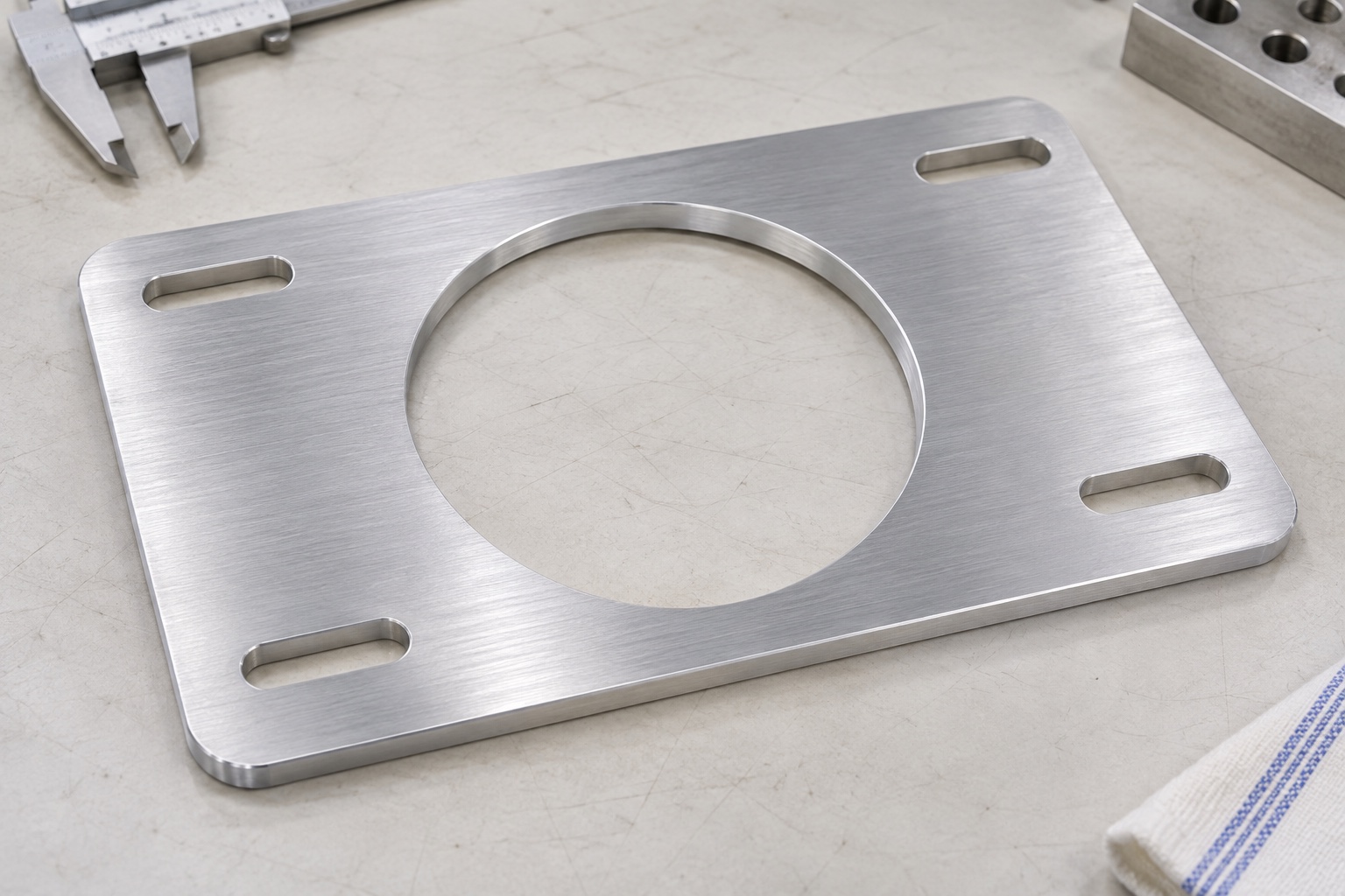
6061 CNC milling for a patient warming unit blower plate concerns a specified mechanical mounting component. The representative part is a rectangular aluminum plate with a central circular opening and four mounting slots outside the opening. This guide discusses fabrication and dimensional inspection of that geometry. It does not prescribe assembly, electrical work or operation of a warming device. The part name does not establish airflow, temperature control, vibration behaviour or patient safety. The responsible device organization must define the actual blower interface and acceptance requirements. A supplier should quote a controlled plate rather than infer an entire system from a photograph or an application label.

Identify the useful seating regions
A plate may have several surfaces that appear flat but serve different functions. Identify which regions contact the approved mount and whether acceptance concerns the entire face or specified pads. Overall thickness does not establish the flatness or relationship of those contacts. State the datum scheme and the required free or mounted condition. A supplier should not select an arbitrary support arrangement because it produces an attractive reading. If the adjacent housing determines the seating definition, include its approved geometry. Clear contact regions allow machining and inspection to discuss the same interface instead of treating every point on the plate as functionally equivalent.
Define the central opening as a mechanical envelope
The central opening needs a size, position and edge condition relative to the mounting references. Clarify whether it locates another component or only provides clearance. A large circular cutout must not automatically be interpreted as a precision locating bore. The supplier should receive the approved neighbouring envelope where it governs interference. Any required keep-clear region should be stated explicitly. This article does not derive airflow performance from the opening area or recommend changing a blower aperture. Mechanical geometry and device-level flow evaluation are separate requirements, even when the same opening appears relevant to both during a design review.
Specify slot length, width and end conditions
Mounting slots require more than a nominal width. Define useful length, orientation, position and the permitted end geometry. Distinguish slot travel from the overall outline and identify any regions excluded by edge finishing. A bolt passing through one point does not verify the complete slot or the mounting pattern. Supply the approved hardware and interface where they influence contact. Do not assume that slots permit unrestricted adjustment or that a convenient position proves correct installation. The manufacturing package should establish the geometry to be accepted without asking a machinist to choose the final alignment of a medical device subsystem.
Confirm material and the post-treatment state
Specify the required 6061 condition, stock form and material documents. The alloy number alone does not define every property or finish requirement. If a treatment or marking operation is approved, identify dimensions and surface conditions that apply afterward. A coated appearance does not demonstrate electrical insulation, corrosion performance, cleaning compatibility or device qualification. Keep the final acceptance state tied to the drawing revision. A pre-treatment slot measurement should not silently stand in for evidence of a finished slot whose requirement applies after treatment. Where requirements conflict, resolve them before production rather than allowing a supplier to choose which stage to report.
Review material removal around the remaining webs
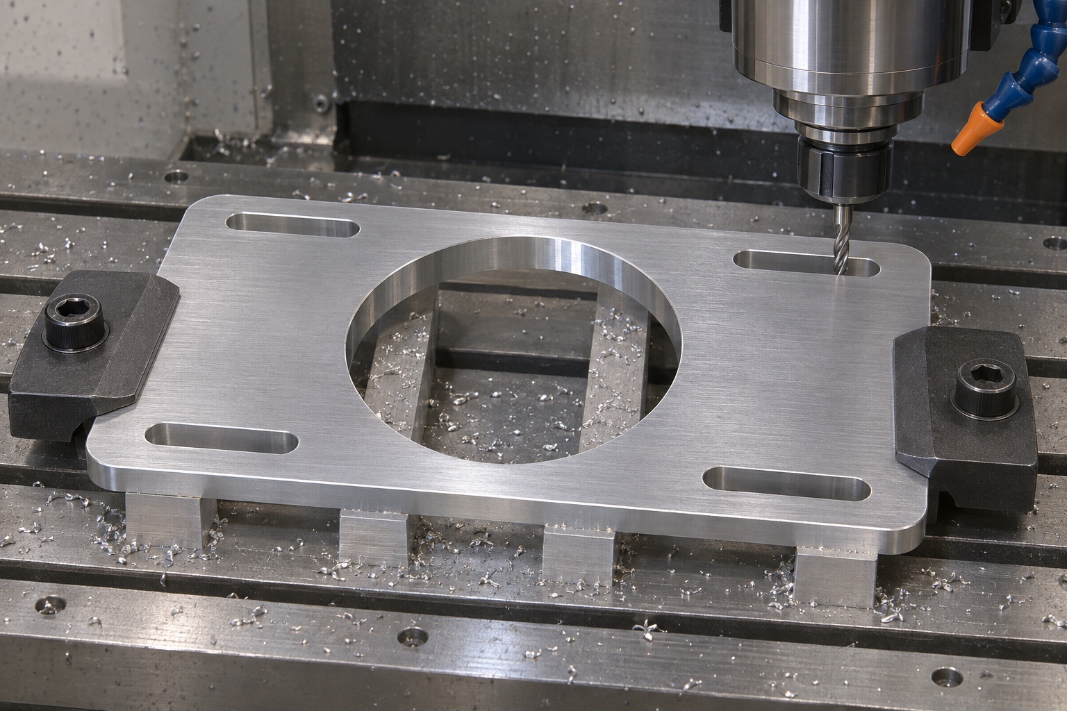
The process review should consider stock support and the material left around the central opening and slots. Cutting a large opening changes how the plate can be held and supported. The actual sequence depends on dimensions, blank and equipment; no universal cutting parameters or stress-relief treatment are prescribed. Identify useful references that need protection during later work. Resolve tool and inspection access before committing to a route. A faster sequence is not automatically a more conforming process. The plan must still account for the finished plate after operations that could influence seating geometry or the relationship between openings and mounting features.
Do not use clamping to manufacture a passing reading
A plate constrained against a fixture may show a different form after release. Review support area and clamp position, particularly near narrow remaining sections. Machining workholding should not become an unrecorded acceptance condition. If the drawing requires measurement in a specified mounted state, reproduce its approved details separately from the production clamp. Do not tighten arbitrary fasteners until the plate appears flat. When readings disagree, review support, reference recovery and the defined condition before removing more material. The goal is a reproducible component against controlled requirements, not a favourable measurement created by force or an undocumented fixture arrangement.
Finish opening and slot edges without losing geometry
The central opening, slot ends, mounting contacts and outside perimeter need an agreed edge condition. Remove raised material without erasing a useful slot length or altering a defined seating band. Identify checks that must be repeated after finishing or treatment. Loose material should be removed from openings before reference comparisons. Ordinary chip removal is not a validated cleaning process, and protective wrapping does not establish sterile supply. Any special cleanliness requirement needs its own approved scope and evidence. Keep marking and identification outside working contacts where possible so traceability does not obscure the geometry that manufacturing and inspection are required to evaluate.
Distinguish form inspection from thickness readings
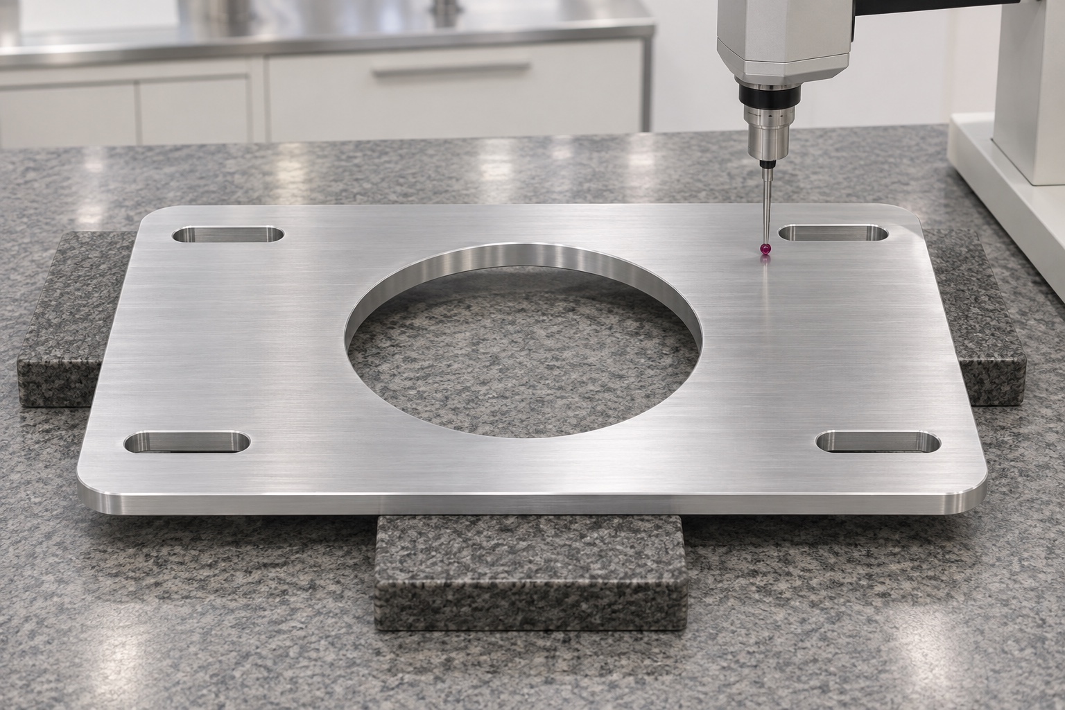
The inspection matrix should separate thickness, useful seating form, opening size and position, slot dimensions and mounting-pattern relationships. Select methods according to access and the actual characteristic. A handful of thickness readings does not establish plate flatness. A coordinate or optical system still needs the approved reference scheme and part state. Record instrument identity, revision and actual results for identified parts. This guide invents no tolerances or measurement values. Resolve any limitation before production so a generic note about precision inspection does not conceal a required feature that was never evaluated in the condition specified by the drawing.
Keep inert interface comparisons limited to geometry
An identified inert blower-shaped reference or approved mounting envelope can help observe contact and clearance without fitting electrical equipment or operating a warming unit. Record reference geometry, support and orientation. A passing hardware trial does not establish airflow, vibration isolation, noise, thermal control, electrical safety or patient warming performance. Those questions require separate device-level requirements and evidence. Do not force a reference through a slot or assume that an adjustable pattern eliminates all alignment requirements. Keep the reference identity associated with the observation, especially when another trial uses a different spacer, support or mounting envelope.
Diagnose rocking before changing the slot pattern
If an inert interface appears to rock or contacts the opening unexpectedly, review seating regions, support, reference alignment, slot definition and edge conditions. Enlarging every slot may conceal a local contact issue while changing the intended mounting interface. Preserve the original observation and distinguish a manufacturing deviation from inconsistent design information. The former requires authorized disposition; the latter requires clarification or revision. Reinspect affected characteristics after approved correction in the specified final state. A later trial made under different tightening or support should not be presented as an equivalent comparison unless those changed conditions are clearly recorded.
Prepare a controlled RFQ and transport arrangement
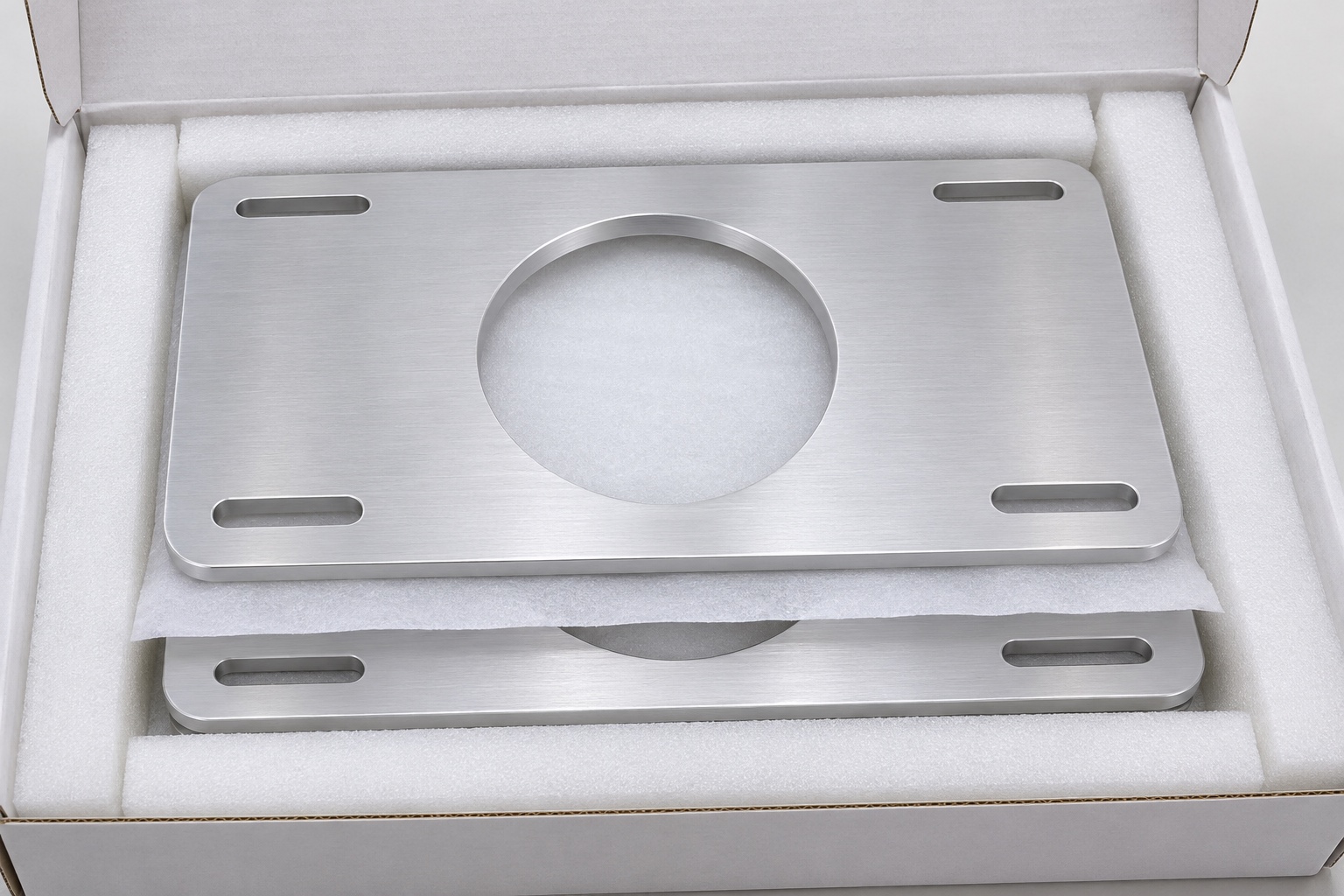
A complete enquiry includes approved model and drawing, revision, 6061 condition, quantity, seating definition, central opening, slot pattern, neighbouring envelope, final treatment, inspection evidence and packaging requirements. Identify acceptance stages where later operations affect useful geometry. Separate plates so edges and seating faces cannot strike adjacent parts. Support should avoid bending the remaining webs or leaving fragments in slots. Keep identity and records associated with the shipment. This gives a medical equipment machining supplier a defined plate to quote while leaving blower selection, device assembly and warming-system performance with the responsible organization and its separate evaluation process.
FAQ
Does plate thickness establish flatness?
No. Thickness and surface form are different characteristics. The useful seating region and the specified free or mounted inspection state must be defined separately.
Is the central opening automatically a locating bore?
No. It may provide clearance only. The approved design must identify its role, size, position and relationship to surrounding components.
Is slot width enough for inspection?
No. Useful length, orientation, position and end conditions may also require checks. A fastener passing at one point does not establish the whole pattern.
Does an inert mounting trial prove warming performance?
No. It records mechanical contact and clearance, not airflow, vibration behaviour, thermal control, electrical safety or the performance of a patient warming system.
Can a plate be tightened flat for acceptance?
Only a defined approved mounted condition can be used where specified. Arbitrary clamping is not a substitute for verifying the required final-state geometry.
What information should accompany the enquiry?
Provide controlled files, material condition, quantity, seating and opening definitions, slot pattern, relevant mating envelope, final finish, inspection scope and protective packaging.

tanghangyun@oemach.com