
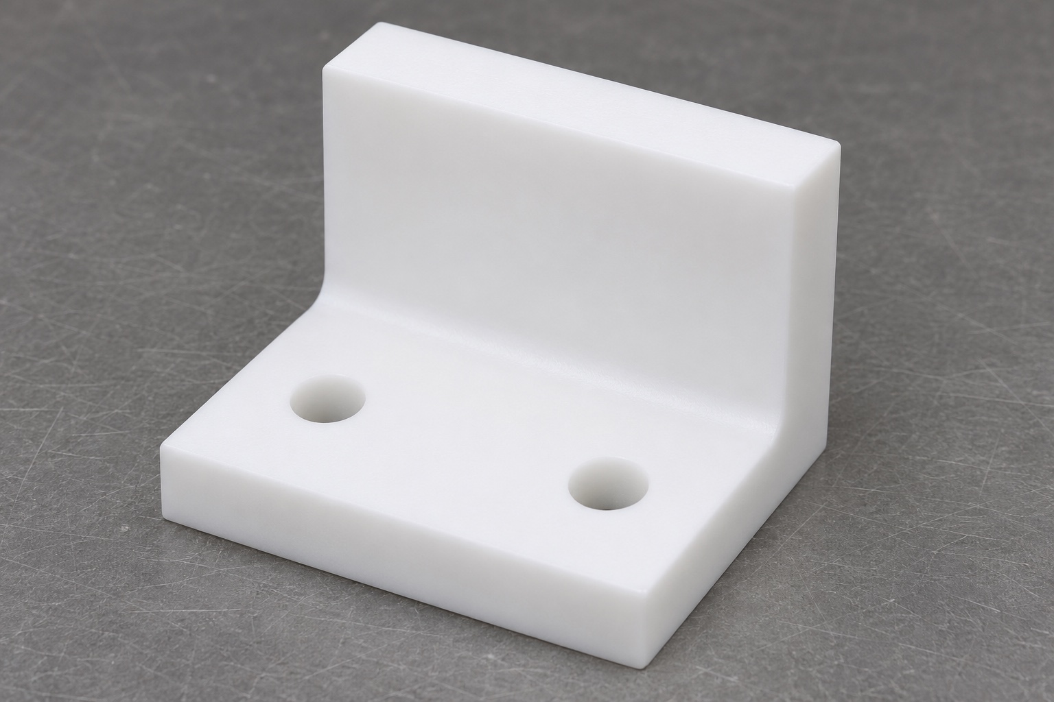
Understand the rack stop as a mechanical reference
A laboratory slide stainer rack stop is a small mechanical part that can define where a carrier contacts a fixed boundary. The representative component here is a white POM-C L-shaped block with a rectangular base, a short upright wall, two base mounting holes and a relieved internal transition. Its critical relationships concern the mounting surface, contact face and available corner clearance. Precision plastic machining should support those relationships without assigning the block responsibilities it does not have. This article does not claim that the component controls staining quality, validates a laboratory workflow or fits a specific instrument.

Distinguish a stop surface from a guiding surface
Begin the drawing review by identifying where the rack is intended to touch and where it must remain clear. A stop face may define an end position while another component guides motion; confusing those roles can create unnecessary constraints. Define the contact region and its relationship to the mounting base rather than asking for every face to receive the same tolerance. If the rack contacts only part of the upright wall, show that region or provide the mating envelope. Do not assume that a visually square block will provide the assembly's required reference without specified acceptance criteria.
Identify the exact POM-C material requirement
POM-C is a useful material designation for a machining discussion, but the actual purchase specification should define the required grade, supply condition, color and traceability. A white acetal stock shape should not be accepted solely because its appearance matches a photograph. Consider whether documentation or restrictions apply to the downstream environment. Chemical exposure, cleaning method and operating temperature need evaluation against the chosen material and complete assembly. This guide does not assert compatibility with staining reagents. A supplier can quote an identified material and process; it cannot validate an unspecified laboratory exposure by using a familiar polymer name.
Establish a stable mounting reference first
The base underside is a natural candidate for the primary mounting reference when the drawing confirms that role. A CNC milling sequence can establish that surface and the features used to locate later operations. Polymer workholding needs enough support to prevent the block from bending into the fixture and springing away after release. Clamping force, contact area and part projection should suit the geometry. Avoid interpreting a dimension measured under heavy restraint as the free-state condition. The inspection plan should state the intended measurement state where deformation could change the apparent relationship between base and stop face.
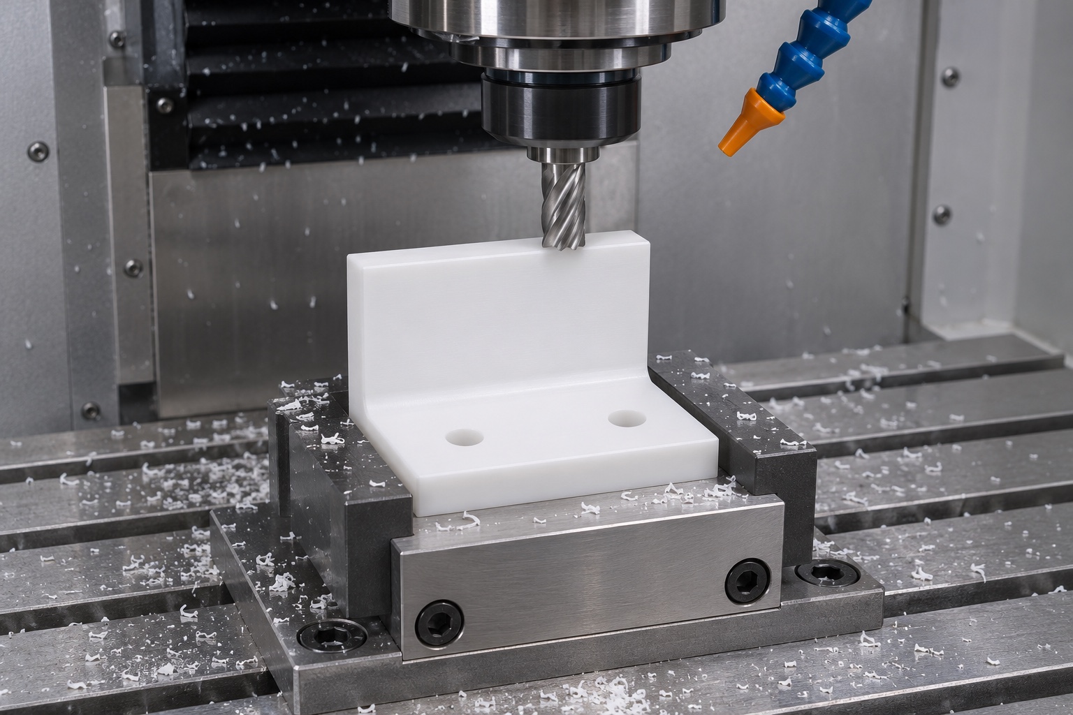
Machine the contact wall with access in mind
The upright wall requires tool access to its contact face and the adjacent base region. Cutter diameter, reach and fixture clearance influence whether the intended transition can be produced without loading a thin section excessively. Use a roughing and finishing plan appropriate to the approved stock and geometry rather than relying on a single aggressive pass. A finishing operation should reference the features that determine installation. If a wall is slender or poorly supported, discuss the design and method before production. Do not replace a difficult-to-machine requirement with a more convenient shape unless the designer authorizes the change.
Define the internal transition instead of assuming sharpness
An internal corner between base and wall often needs a radius or relief because a milling cutter cannot create every theoretical sharp corner directly. The required corner clearance should follow the mating rack geometry. A controlled relief can allow the intended contact face to engage without interference, but its location and extent belong in the design requirements. Avoid adding an arbitrary groove simply because it simplifies machining. The review should identify whether a corner is functional, noncontacting or used only for access. That distinction helps prevent an unnoticed corner mismatch from being mistaken for a stop-height error during assembly.
Relate mounting holes to the installation strategy
Two mounting holes in the base do not automatically establish a repeatable position. Clearance, fastener arrangement and the actual locating features determine how the block sits in the assembly. Specify hole size and position in relation to the approved reference structure. If adjustment is intended, the design must define how that adjustment is achieved; this example retains two round holes and does not silently substitute slots. Consider access for machining, inspection and installation together. Requirements for tightening, inserts or mating hardware should come from the assembly design, not from a generic plastic machining recommendation.
Manage heat and relaxation during polymer machining
Plastic parts can respond to machining and restraint differently from metal parts. Cutting conditions, tool condition, chip removal and the support arrangement should be selected for the identified POM-C stock and component geometry. A dimension observed immediately after a heavily restrained operation may not describe the released part under the agreed inspection conditions. Where the application warrants it, the process plan should define when and how the part is checked after machining. Avoid inventing a universal conditioning time or claiming that one parameter set guarantees stability for every acetal grade, blank size and laboratory equipment design.
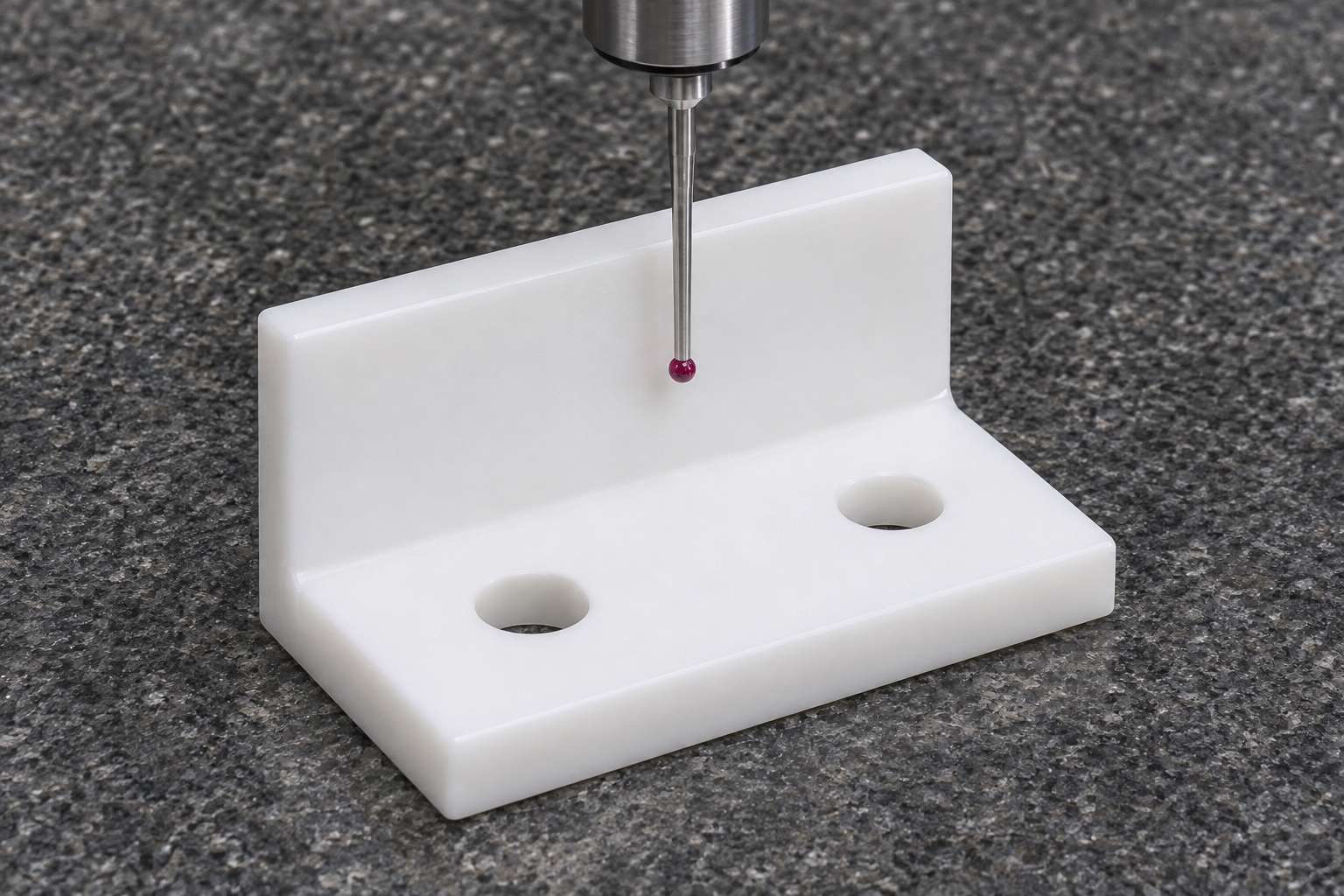
Choose inspection methods for the contact relationship
Inspection should address the mounting plane, contact-face orientation, stop height, hole locations and specified corner clearance. Select methods with suitable access and contact force for the part. A probe or fixture can distort a polymer surface if its loading is inappropriate; a noncontact method may help for some features but still needs a defined reference alignment. Record the actual acceptance characteristics rather than describing the part only as precision machined. For prototype evaluation, compare the manufactured geometry with the controlled requirements first, then evaluate assembly fit separately with the correct mating rack and installation conditions.
State surface and edge requirements by function
The contact face may need a different finish from an exterior that never touches the rack. Define unacceptable projections, chips or raised edges where they could affect seating or handling. General deburring should not round away a controlled contact boundary. If appearance matters, agree a visual reference or explicit criteria before production. A smooth white surface does not establish cleanability, reagent resistance or a validated laboratory cleaning process. Keep those topics separate from ordinary machining finish so the supplier knows which evidence is required and the buyer does not interpret a cosmetic inspection as proof of functional suitability.
Keep handling and packaging consistent with acceptance
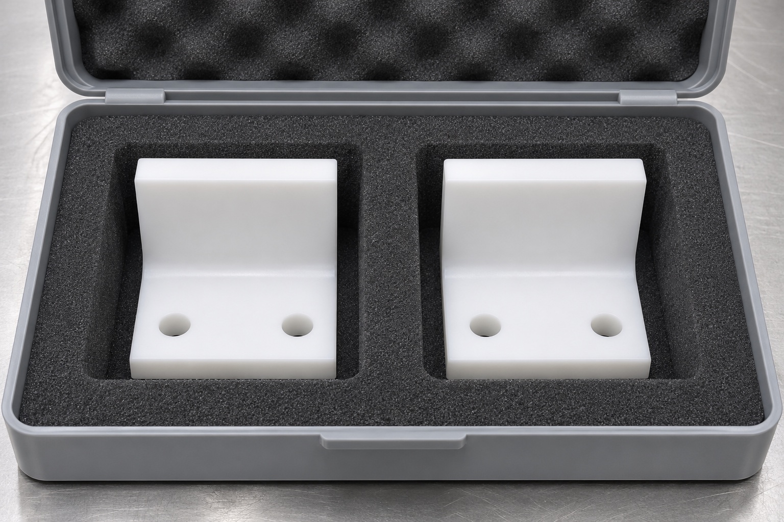
After approved final preparation, protect the upright wall and contact face from impacts or sustained loading in transit. Separate pockets can keep mounting holes and contact edges away from loose hardware. Packaging materials should suit the agreed cleanliness and downstream handling requirements. Do not attach a label across the contact face or use a packing arrangement that bends the wall. A photograph can document the physical arrangement, but a real shipment record must identify the actual material and lot. Ordinary protective packing does not establish sterility or a special cleanliness classification unless those requirements are separately specified and supported.
Build a practical RFQ for custom acetal stops
An RFQ for POM-C CNC milling should include the drawing and model revision, material identification, quantity, mounting reference, contact region and corner-clearance requirements. Request a clear inspection scope and identify whether assembly checking is included. Ask the supplier to explain any assumptions about polymer restraint, measurement condition and finishing access. Compare offers against that shared scope rather than a generic promise of tight tolerances. A prototype review can resolve fit and handling questions before recurring production, but any approved change should be reflected in controlled documents so later batches are not made against informal recollections.
FAQ
Does POM-C identify a complete material specification?
No. The required grade, supply condition, documentation and relevant restrictions still need definition. Color or a generic acetal description alone is not enough to establish that the supplied stock meets the purchase requirements.
Can this guide establish staining reagent compatibility?
No. Actual chemical exposure and cleaning conditions require material and system evaluation. The machining guidance concerns geometry and acceptance; it does not validate a reagent, cleaning process or laboratory instrument workflow.
Why include an internal corner relief?
A defined relief can provide clearance for a mating rack when the design requires it. Its extent must be approved; adding an arbitrary groove or removing a functional contact edge is not an acceptable assumption.
Should dimensions be checked while tightly clamped?
Only if that is the agreed measurement condition. Restraint can distort a polymer part. Inspection should describe the relevant state and reference alignment so results represent the condition required by the drawing.
Do two mounting holes guarantee repeatable positioning?
No. Positioning depends on the complete installation design, including clearances and locating features. Hole presence alone does not establish the final stop position, fastening performance or permitted adjustment in the equipment.
What distinguishes a useful prototype review?
It separates dimensional conformity from assembly fit and documents any approved change. The review uses the correct rack, installation references and acceptance criteria rather than relying only on visual resemblance to a model.

tanghangyun@oemach.com