
This article explains why cumulative position error, creep, and backlash can still occur with acceptable gauges, and incorporates thread geometry, mating surfaces, lubrication, and support conditions into the same verification scheme.
Qualification of fine-tuning threads cannot be determined by a single pass-stop gauge; actual mating parts must be used to verify the full stroke lead, forward and reverse backlash, and starting/running torque under specified conditions. The specific process still needs to be confirmed in combination with thread specifications, effective lead, fit level, end support, return clearance, friction torque and measurement uncertainty.
Typical problems, causes, controls and evidence
| Problem | Likely cause | Control action | Acceptance evidence |
|---|---|---|---|
| Accumulation of position errors throughout the entire stroke | Progressive lead error caused by pitch system error, machine tool transmission or thermal state | Processing at stable temperature and calibrating the lead according to the effective stroke | Multi-position linear displacement or angular displacement error curve |
| Fine-tuning may cause crawling or inconsistent feel. | Surface, lubrication, fit and axis deflection combine to change frictional torque | Pair finishing and fixing cleaning, lubrication and assembly conditions | Forward and reverse starting/running torque and repeatability records |
| Access and stop specifications are acceptable but return clearance is large | Gauges do not cover actual mating clearance and support tolerances | Add representative nut pairing and system-level hysteresis verification | Mating clearance, axial play and backlash data |
Lead error will directly become displacement error
The fine-tuning mechanism converts rotation into axial displacement, and the actual advancement of the thread per revolution determines the position. Progressive, local and periodic lead errors manifest themselves as proportional deviations or fluctuations at different locations. The project should specify the effective stroke, sampling position and error evaluation method, and cannot only check the nominal pitch. Processing machine tool transmission, thermal conditions, tool and mounting eccentricities can all enter into lead errors.
Effective diameter and tooth shape affect fit and load
The effective diameter determines the thread flank contact location, while the profile angle, flank surface and roundness affect load distribution. Go-no-go gauges are suitable for judging specific limits, but generally do not fully describe full stroke lead, backlash or friction. Precision fine-tuning parts should be combined with three-pin method, image/CMM or special thread measurement, and the measurement uncertainty and temperature conditions should be clearly defined.
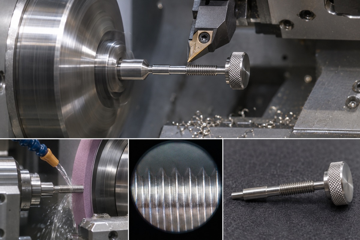
The thread, bearing journal and end functional surface should maintain a common axis.
Friction torque is not as small as possible
Too much torque may cause crawling and adjustment fatigue, while too little torque may cause rollback under vibration. Starting and operating torques are also affected by material combination, roughness, surface treatment, lubrication, preload and axis deflection. Friction is a system result, and you cannot just label a single screw with a "feel" requirement. Testing shall be conducted in pairs with representative nut, support and assembly conditions.
The processing route should protect the thread axis
The supporting journal, end ball head or thrust surface of the precision screw should be consistent with the thread axis. If different temporary datums are used for thread machining and journal finishing, periodic resistance will be formed after assembly. Turning, grinding or grinding can be arranged under a stable center reference, the bending and effective dimensions can be re-measured before and after heat treatment or surface treatment, and the tooth flanks can be protected from being bumped.
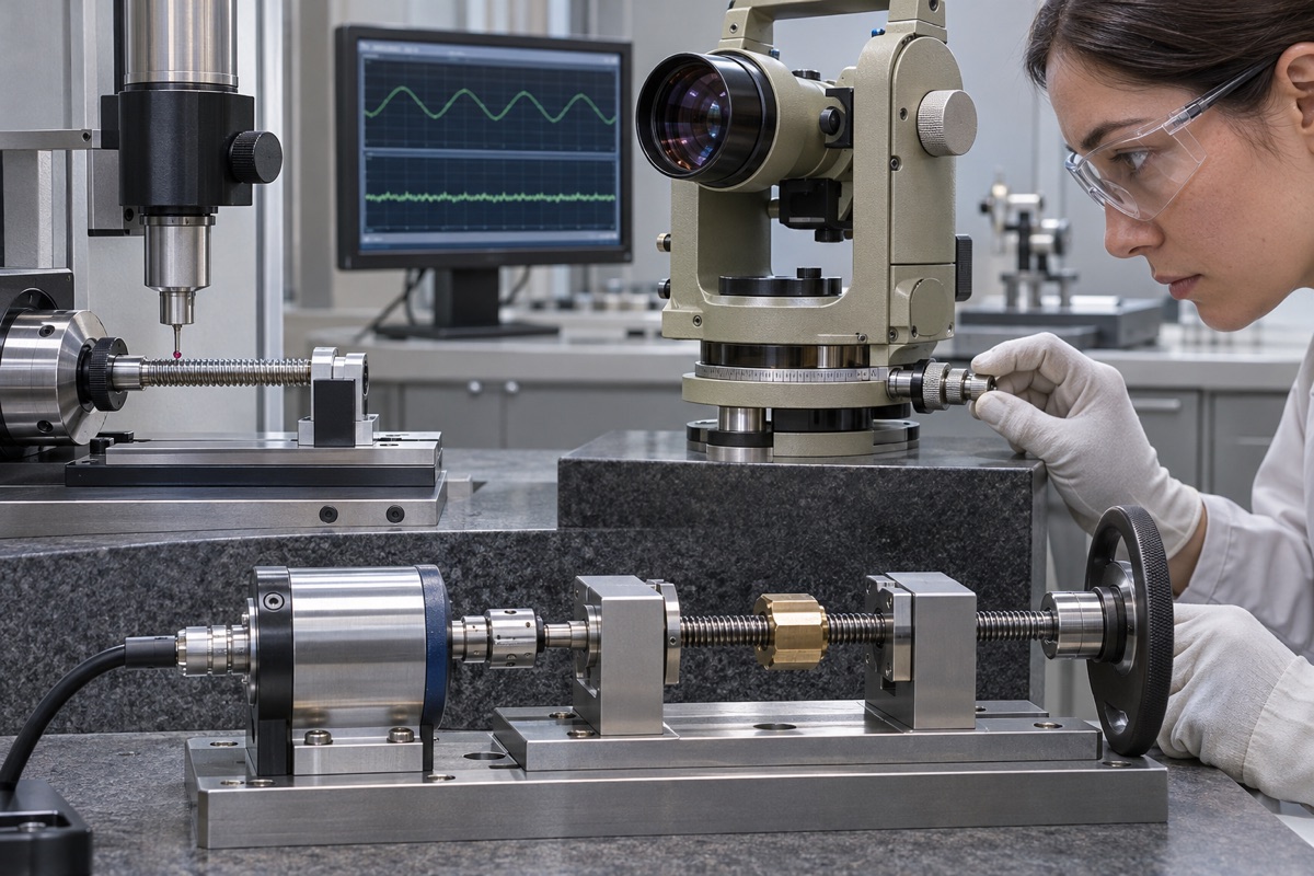
The displacement curve and forward and reverse torques need to be recorded under fixed pairing and lubrication conditions.
Matching, cleaning and lubrication must be standardized
If the same screw is replaced with a different nut, the torque and backlash may change; cleaning residue and lubrication amount will also change the results. Mass production requires matching rules, cleaning methods, lubricants and application amounts, running-in strokes and inspection speeds. If the project requires a vacuum or low-precipitation environment, the system responsible party must confirm the materials and lubrication plan, and ordinary engine oil cannot be used.
Complete acceptance using displacement and moment curves
An angle encoder and displacement measurement are used to construct a full-stroke lead curve, and a calibrated torque device is used to record forward and reverse starting/running torques. Range, resolution and calibration should match the requirements. NIST data indicates that lead error will affect fit and load distribution; specific product limits still need to be determined by the agency's error budget and user experience goals.
Summary
Qualification of fine-tuning threads cannot be determined by a single pass-stop gauge; actual mating parts must be used to verify the full stroke lead, forward and reverse backlash, and starting/running torque under specified conditions. The specific process still needs to be confirmed in combination with thread specifications, effective lead, fit level, end support, return clearance, friction torque and measurement uncertainty.
FAQ
Are the pass and stop regulations sufficient?
Not enough. It usually does not cover full travel lead, pairing hysteresis and friction torque.
The lower the torque, the more precise the adjustment?
Not necessarily. If it is too low, it may loosen by itself; if it is too high, it may crawl. The window should be determined according to the preload, vibration and operation methods.
Can the screw and nut be paired randomly?
Depends on the design. High-consistency fine-tuning mechanisms typically verify interchangeability or establish controlled pairing rules.
Ready to get a quote for your CNC machined parts?
Submit your engineering drawings to qiancj@oemach.com. We support prototype sampling and small-batch production with strict tolerance control.