
This article explains how the aspect ratio hole system establishes a stable mechanical axis, and why it is still necessary to use autocollimation or the actual optical path to retest after the lens and target plate are installed.
Mechanical coaxiality is a necessary condition but not the final conclusion; the key hole and the end face should be machined on the same basis, and the true optical axis should be verified using optical methods after assembly. The specific process still needs to be confirmed by combining the axis of the collimator tube, the stop of the mirror holder, the target plate datum, the verticality of the end face, the step difference of the inner hole, the assembly and adjustment allowance, and optical retesting.
Typical problems, causes, controls and evidence
| Problem | Likely cause | Control action | Acceptance evidence |
|---|---|---|---|
| Mechanical coaxiality is qualified but the light spot is offset | Lens optical axis, mounting stress, or target board attitude are not covered by the mechanical report | Additional self-collimation/actual optical path verification after mechanical inspection | Hole system coaxiality, target attitude and light spot data |
| The inner hole step difference after turning over | Datum conversion and aspect ratio machining introduce axis offset | Try to complete the key holes and set the restorable datum with the clamping | Multi-section bore and end squareness reports |
| Collimation changes after locking the lens group | Uneven pressure or contamination of the contact surface causes the lens assembly to tilt. | Limit hold and fix cleaning and locking sequence | Optical retest and assembly records before and after locking |
First establish the mapping between the mechanical axis and the optical axis
The functional axis of the collimator is formed by the objective lens, collimation tube, reticle or target plate. Mechanical drawings should define the relationship between the lens mount stop, bore, end face, and external mounting surface, and indicate which features represent the optical center. Multiple holes are only given their own sizes without a common benchmark. The manufacturing end cannot determine which axis is the most important, and can only rely on large-scale compensation during assembly and adjustment.
Long hole processing is prone to taper and step differences
The collimation tube usually has a large length-to-diameter ratio, and the deflection of the tool bar, thermal elongation, chip removal and turning over for alignment will cause taper, drum shape or axis breakage. It can be controlled through stable support, staged boring or honing, and the mirror base stop and key inner hole can be completed in one clamping. When both ends must be machined, a recoverable datum must be designed and the multi-section axis measured.
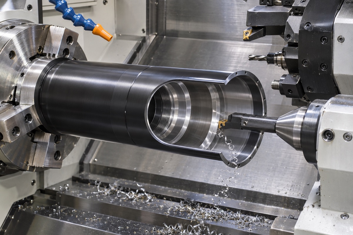
The long hole, stop and end face should be completed around the common mechanical axis.
The end face and stop determine the lens posture
The axial position of the lens is controlled by the step end surface, and the radial position is controlled by the stop or lens holder. End face verticality, contact width, chamfers and pressure ring threads all affect tilt after installation. Surface treatments or matt coatings must not be deposited on functional contact surfaces. Before assembly, check for burrs, particles and cleanliness to avoid using pressing force to correct bad contact.
The target board bracket should control the position and angle at the same time
Even if the target plate center falls near the tube axis, plate tilt will change imaging and collimation results. The mounting surface, positioning holes and adjustment mechanism of the bracket should be designed around the same datum, leaving a verifiable adjustment margin. After locking, recheck the position and attitude to prevent rebound caused by the adjusting screw and spring pretension.
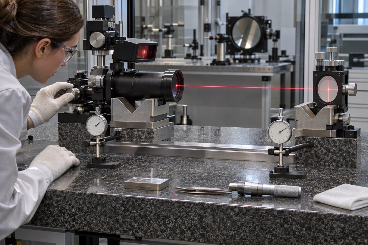
The final optical axis needs to be re-measured after the lens assembly and target board are assembled.
Materials and temperature affect long tube axis
Aluminum alloys are good for weight reduction, but have greater thermal expansion; steel or low-expansion materials have different quality, cost and processing characteristics. Material selection should be determined by operating temperature zone, length, settling time, and system error budget. The temperature must be recorded during processing and inspection. Long parts may also have shape differences due to their own weight under different support directions.
Finally, optical retest was used to confirm the system
Mechanical reports can demonstrate the geometric relationship of bore axes, end faces, and target plate datums, but cannot cover lens wedge angles, assembly stresses, and actual optical centers. Verification after assembly should be performed using autocollimator, interferometry, or project-approved optical methods. If the mechanical and optical results are inconsistent, the cause should be located along the datum chain instead of arbitrarily expanding the mechanical tolerance.
Summary
Mechanical coaxiality is a necessary condition but not the final conclusion; the key hole and the end face should be machined on the same basis, and the true optical axis should be verified using optical methods after assembly. The specific process still needs to be confirmed by combining the axis of the collimator tube, the stop of the mirror holder, the target plate datum, the verticality of the end face, the step difference of the inner hole, the assembly and adjustment allowance, and optical retesting.
FAQ
Whether the mechanical coaxiality is qualified must be aligned
Not necessarily. The optical axis is also affected by the lens itself, the hold, and the target board attitude.
Can long tubes be processed separately at both ends?
Yes, but you need to have a recoverable datum and verify the relationship between the two axis lines and the end faces.
Can the black matte treatment cover the inner hole reference?
It should be masked and re-inspected according to the design, and the treatment layer cannot damage the lens holder stop and functional contact surface.
Ready to get a quote for your CNC machined parts?
Submit your engineering drawings to qiancj@oemach.com. We support prototype sampling and small-batch production with strict tolerance control.