
Based on THK guide rail selection and installation data, this article explains that the preload must match the load, stiffness and installation accuracy, and that greater preload cannot be used to cover up base processing errors.
Preloading can improve stiffness but not free accuracy; installation errors will translate into additional internal loads, resistance and life risks, and should be approved based on full-stroke geometry and operating data. The specific process still needs to be confirmed by combining the guide rail model and preload level, reference shoulder, mounting surface shape, double rail parallelism, locking sequence, running resistance and working load.
Typical problems, causes, controls and evidence
| Problem | Likely cause | Control action | Acceptance evidence |
|---|---|---|---|
| The slider runs tight after assembly | The double rails are not parallel or the installation surface error is superimposed on the preload | Control the common reference and lock it in sequence, and retest while sliding | Full stroke running resistance and post-locking geometry records |
| After increasing the preload, the repeatability becomes worse. | Friction, mounting errors and local load rise | Select preload according to load and stiffness requirements, and do not use preload to compensate for machining errors. | Start/run resistance, repeatability and temperature rise data |
| Single track passable but double track platform twisted | Separate alignment without controlling common plane and lateral datums | The main rail establishes a benchmark, and the auxiliary rail is adjusted and verified according to the motion state. | Dual track parallelism, table shape and running accuracy reports |
The essence of preload is the internal load of rolling elements
Preloading improves stiffness by eliminating internal gaps, making displacement more controllable under external loads. THK data points out that radial clearance will affect running accuracy, load-bearing and stiffness, and should be selected according to the application. When the preload is too large but the installation error is encountered, the rolling element load and friction will increase, so "tighter" cannot simply be equated with "more accurate". The specific grade should be determined by the rail model, load, vibration and life requirements.
Installation surface error will amplify the side effects of preloading
The bottom surface of the guide rail is uneven, the lateral reference is not straight, or the two rails are not parallel, which will force the slider to continuously adjust its attitude during the stroke. A lightly preloaded system may exhibit resistance fluctuations, while a medium/high preloaded system may produce significant tightness and local loads. The processing of the mounting surface should control the straight, parallel and perpendicular relationships with a common reference, and avoid burrs, dents and particles.
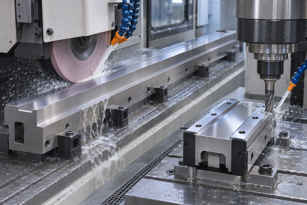
The two rail mounting surfaces should reference a common datum and control the overall shape.
The reference shoulder and fillet must match the guide rail
If the corner fillet of the base is larger than the chamfer of the guide rail, the guide rail cannot be close to the reference surface; the offset of the mounting hole will also pull the guide rail off during tightening. THK installation materials specifically remind you to remove burrs, dents and dust, and check for misaligned bolt holes. During design and processing, side shoulders, fillets, counterbore holes and thread depth should be set according to the specific guide rail drawings.
Dual-track assembly first establishes a master-slave relationship
It is easy to obtain two "best straight lines" that are inconsistent with each other by independently aligning the two guide rails. Usually, the main rail is used to establish the reference first, and then the auxiliary rail is adjusted while the platform is sliding. The bolts are gradually tightened from the middle to both ends or according to the manufacturer's procedures, and the specified torque is used. Continuously observe the resistance and table posture during the assembly process to detect local warpage early.
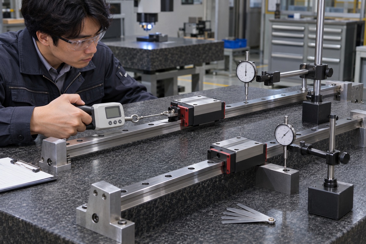
The preloading effect needs to be evaluated in combination with locking status, resistance and movement accuracy.
Movement accuracy cannot only measure no-load straightness
The robot mechanism operates under load, acceleration and attitude changes, and the slider combination, table stiffness and driving force all affect the movement. Acceptance can include full travel straight line, pitch/yaw, running resistance, repeatable positioning and temperature rise, and specify load and speed. Individual mounting surface flatness or no-load hand push feel are no substitute for system results.
Measurement results should be consistent with guide rail manual
THK provides examples of measuring operating accuracy with an autocollimator or indicator after installation. The project should select measuring tools according to the guide rail model, length and structure, fix the support, lock and measure the path. Public articles do not provide unified preload or parallelism values. The final requirements should come from the guide rail supplier, complete machine error budget and prototype verification.
Summary
Preloading can improve stiffness but not free accuracy; installation errors will translate into additional internal loads, resistance and life risks, and should be approved based on full-stroke geometry and operating data. The specific process still needs to be confirmed by combining the guide rail model and preload level, reference shoulder, mounting surface shape, double rail parallelism, locking sequence, running resistance and working load.
FAQ
The greater the preload, the more accurate the positioning will be?
Not necessarily. Preloading increases stiffness but increases drag and amplifies installation errors.
Can the slider automatically absorb the base error?
Only limited absorption; high-precision and high-stiffness applications still require reliable mounting surfaces and assembly control.
What should be measured after the guide rail is installed?
At least combine the project to verify the full-stroke operating resistance, linear/angular error, repeated positioning and temperature rise.
Ready to get a quote for your CNC machined parts?
Submit your engineering drawings to qiancj@oemach.com. We support prototype sampling and small-batch production with strict tolerance control.