
Separate the part from the instrument
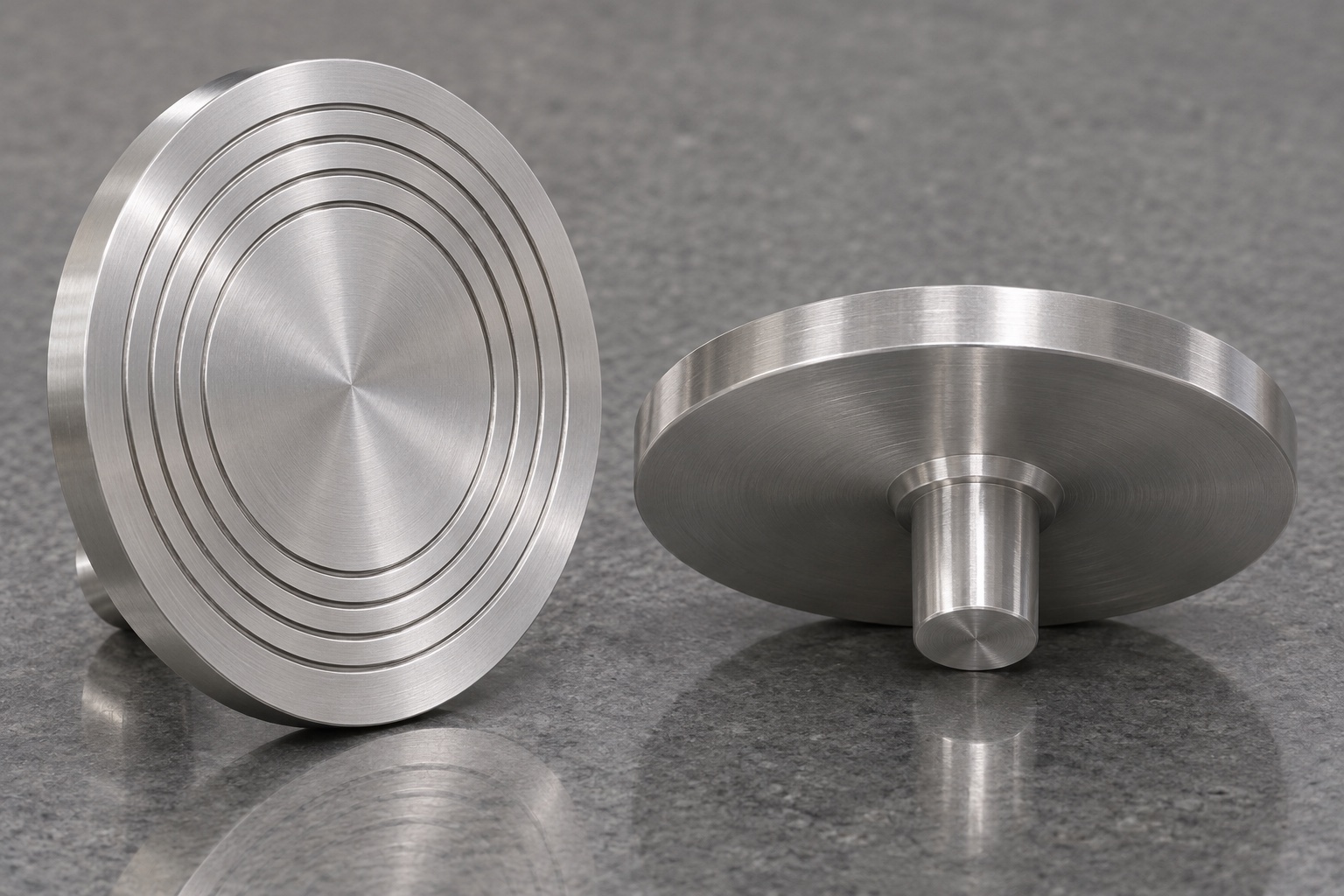
A cryostat specimen disc has a front surface intended to hold material and a rear interface that locates in a mating holder. This guide addresses a representative metal disc with concentric shallow grooves and a central cylindrical stem. It does not specify a replacement for any instrument model. A drawing review starts with the approved holder envelope and the actual seating contacts, not a photograph of a similar disc. The manufacturer and device owner must establish suitability for the intended use. The machining review asks a narrower question: can the chosen geometry be made, measured and delivered without confusing one interface with another?

Identify which rear surfaces locate
The locating stem can establish an axis, while a shoulder against a mating seat can constrain axial position. That description only applies if those surfaces actually contact in the assembly. Ask which portion of the stem carries the fit and where the mating bore ends. A short relief near the shoulder may prevent a radius from bearing against a sharp edge, but it also changes the available contact length. Record the contact portion and relief on the drawing rather than letting a programmer infer both from a solid model. An agreed section view can resolve this ambiguity before setup begins.
Describe the working face without averaging grooves
The front face comprises lands and intentionally recessed channels. A flatness requirement needs to name the lands included in the assessment, whether they are evaluated together, and which grooves or interruptions must be excluded. A probe path that crosses both the lands and the groove bottoms reports a height range, not the flatness of the intended surface. Conversely, points on one small land cannot demonstrate that the entire face is coplanar. Define the relevant radial zones and enough sampling to detect unevenness. Record the measurement strategy so that another inspector can reproduce it without relying on fixture photographs alone.
Distinguish flatness from axial runout
A face can be flat yet tilted relative to the stem. Flatness describes form without a datum. Axial runout measures variation during rotation relative to a defined datum axis; the track radius and contact points matter on a grooved disc. A reading on an outside land may detect a condition that a reading close to the center does not. If tilt or axial variation matters, specify the requirement that describes it and the reference used to establish the axis. Do not substitute a single indicator reading for separate form, size and orientation requirements unless the drawing explicitly accepts that approach.
Plan the turning sequence around access
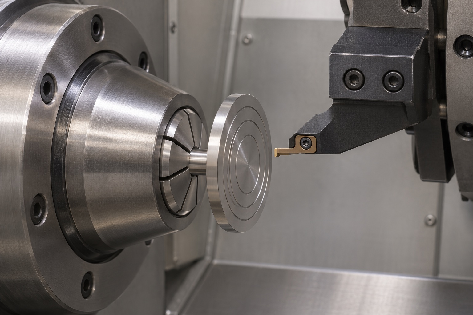
Turning the stem and shoulder in one setup can keep their relationship tied to one spindle axis. Access to the front face may require transfer to a collet, soft jaws or a fixture that references the approved stem and shoulder. Each transfer introduces another location and clamping condition. Check contact length, stop cleanliness and tool reach before selecting an operation order. A thin flange can move under cutting or fixture load even when the stem remains centered. Where useful, leave a controlled finish allowance and compare the disc after releasing it rather than relying only on a reading made under clamping pressure.
Define face groove geometry
Specify groove diameter or radial location, width, depth and any required root or entry radii. These characteristics are not interchangeable with a surface roughness value. Confirm tool clearance at both flanks, especially when using a face-grooving insert that only supports a limited diameter range. Tool nose radius and approach can influence the shape at the bottom of a shallow groove. If the process uses a different insert after maintenance, compare critical cross sections and any edge effects before release. Inspection access is part of manufacturability: a groove with no reachable surface may require optical or profile measurement rather than a conventional stylus.
Specify the material and finish separately
If 316L is selected, identify the applicable material designation, stock condition and required traceability. A nominal grade does not establish thermal response, corrosion behavior in a specific chemical, or suitability for a clinical process. Separate any approved surface treatment from dimensional acceptance. A treatment route may introduce handling marks, change surface appearance or require a repeat check of critical interfaces. Define who approves substitutions and when dimensions are inspected. If another material is proposed for thermal reasons, evaluate it as a design change rather than a machining shortcut; density, conductivity and compatible finishing should be considered by the responsible engineer.
Protect the stem and shoulder during deburring
A burr at the seating shoulder can keep an otherwise correct disc from sitting flat. A broad chamfer, however, can remove the land that the holder needs. Define edge limits at the stem entry, shoulder transition, rim and groove lips. Use a method that reaches the intended edges without rolling metal into grooves or rounding reference lands. Then check under lighting that reveals raised material and trapped chips. A visual check supports edge assessment but does not replace dimensional measurement. A documented boundary between permitted edge break and functional geometry is easier to enforce than a general instruction to make the part smooth.
Check the interface with an inert reference
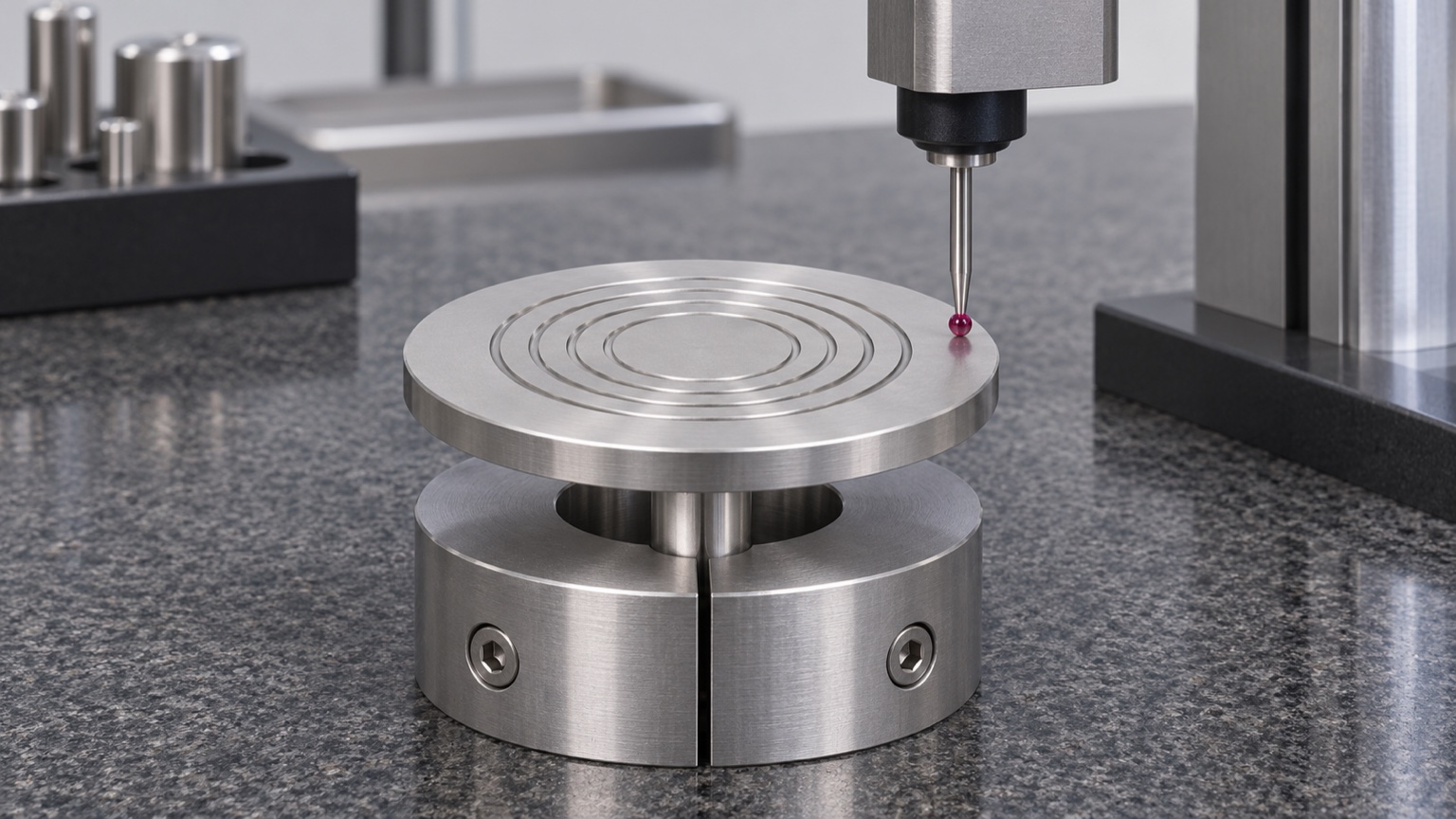
If the device owner supplies an approved gauge or mating reference, use it in a bench fit check without biological material or an operating cryostat. Record the revision, orientation, seating condition and any evidence of interference. A gauge that only accepts the stem does not check shoulder seating or front-face orientation. Inspect the reference for wear and contamination before interpreting inconsistent results. The most useful report identifies which contact failed and whether the dimensional results agree with it. Fitting by force or repeatedly polishing the stem until a sample seats can hide a process problem and alter the agreed interface.
Document measurement uncertainty and condition
Record the measurement equipment, calibration status, part temperature or equilibration condition as required, fixture and data strategy. If a feature is near a limit, consider whether the equipment and setup can resolve the difference and use the agreed decision rule. Room-temperature dimensions are not evidence of the cold assembly behavior. When cold fit, freezing behavior or repeated exposure matter, the equipment owner must specify the conditions and validation. Keep those results separate from the supplier's drawing-conformance report. An explicit limit on what was measured makes the document useful without implying that the disc has been cleared for a particular instrument.
Manage residues and contact in packaging
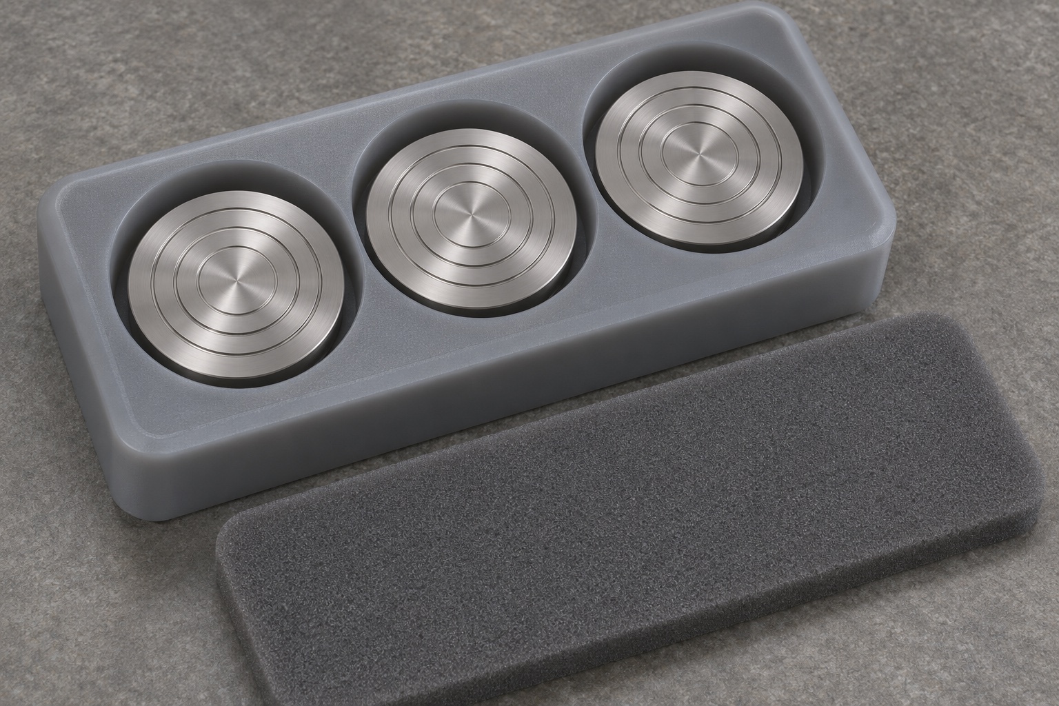
Groove roots can retain particles after turning and finishing. Apply the documented cleaning process appropriate to the material and specified delivery condition, then inspect accessible recesses and the seating interface. Agree which evidence is required for cleanliness and which methods are excluded. Use separate pockets or separators so that disc faces and stems cannot strike one another in transit. Avoid packaging contact on critical lands unless it has been approved. A protected package is not a sterile barrier merely because it looks clean. The label and records should tie the part to the drawing revision and material lot where traceability is required.
Prepare a complete machining inquiry
Send a revision-controlled drawing and model with the approved datum scheme, mating section, groove definition and edge limits. Include the material, finish, anticipated quantity, inspection evidence and packaging conditions. Identify any characteristic that the supplier cannot infer from nominal geometry, such as allowed contact at a shoulder fillet or a specified runout track. Ask for a proposed setup and inspection plan before agreeing to a tolerance that depends on transfer between operations. Separate mechanical acceptance from thermal or clinical validation. That division makes quotes comparable and gives both sides a concrete set of questions to resolve before making representative samples.
FAQ
Does front-face flatness control tilt to the stem?
No. Flatness controls the form of the identified surface, not its orientation to a datum. If tilt or axial runout matters, call out the required relationship and identify how the stem axis is established.
Can the groove bottoms be included in face flatness?
Only if the specification intentionally defines such a surface evaluation. Normally the raised lands and recessed groove geometry are separate checks. Define sampling zones so readings are not taken across unrelated depths.
Is a 316L disc compatible with every cryostat?
No. Material designation does not establish mechanical compatibility, thermal behavior or suitability for a procedure. Verify the approved interface and refer equipment validation to the device owner.
How can a shoulder burr affect bench fit?
A raised burr can become an unintended contact and keep the shoulder from seating. Check the actual contact region and follow the specified edge limits rather than enlarging the chamfer without approval.
Is a cold-condition test part of dimensional inspection?
Not unless it is explicitly specified. A room-temperature conformance report states its measurement conditions. Any cold-condition check needs a separate, agreed test method and acceptance scope.
What should be protected during transport?
Prevent contact between the front lands, grooves, locating stem and other loose parts. Separate retention pockets and revision-linked identification can support delivery protection without claiming sterility.

tanghangyun@oemach.com