
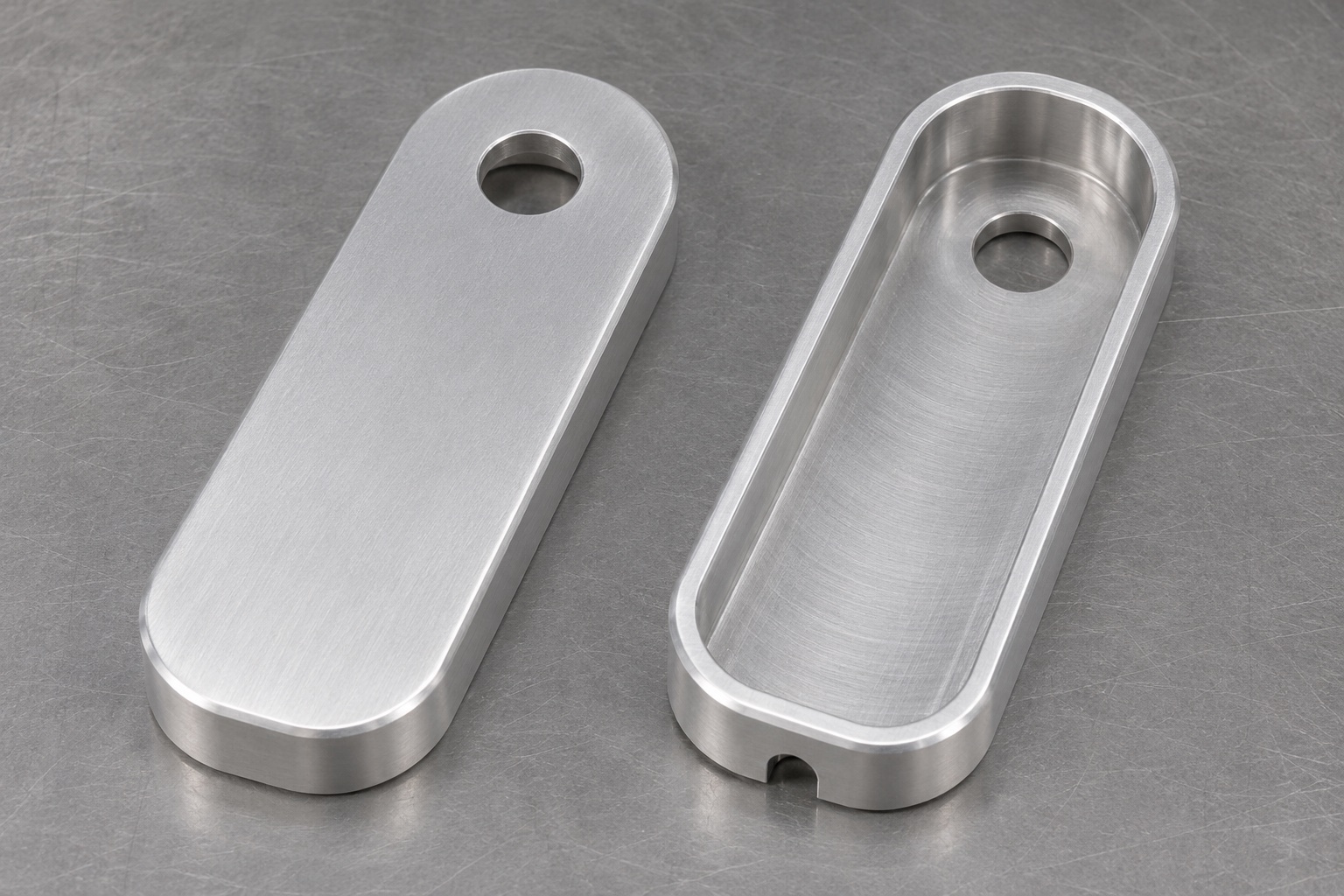
Define what the bare housing does
A response button housing provides mechanical space for an actuator and its associated assembly. The representative shell here is a rounded 6061 body with one circular guide bore, an open rear cavity and a cable clearance notch. It is not a replacement for any named perimeter or a complete response device. A machining review addresses the approved envelope, locating surfaces and workmanship. The equipment owner must define electrical safety, switch behavior, cleaning compatibility and usability. A dimensional report on the shell cannot demonstrate any of those outcomes or establish the accuracy of a visual field test.

Identify the actuator and cover interfaces
Request the controlled envelope of the actuator, its mechanical guide and the rear cover. Determine which feature actually locates the moving element: the visible bore, a separate insert or an internal support. The answer changes how bore position and clearance should be specified. Identify the cover contact plane and which wall surfaces must remain clear. A nominal model of the outer shell cannot substitute for these interfaces. Include the cable and connector envelope if it affects assembly. Record any open design questions before using a gauge or selecting an operation sequence, so the fixture does not invent an interface.
Distinguish diameter from bore position
A circular bore can meet size while its axis is offset from the mating support. Conversely, an axis can be well located while a local taper or raised edge affects travel. Specify the measured portion of the bore and the datum relationship that controls it. A chamfer at entry is not part of the cylindrical guiding surface. Define useful guide length, especially if the bore breaks through a thin cavity floor. A pin can screen some size or interference conditions, but it does not measure axis position. Report size, location and edge condition separately rather than reducing them to one fit result.
Define the rear cavity by clearance zones
The cavity must accommodate the approved internal envelope without removing material needed for wall support or the cover seat. Name the areas where clearance is critical, including corners and transitions. A milling tool leaves an internal radius that can conflict with a square mating envelope. Review the actual geometry before requiring a sharp inside corner. Specify depth from a functional reference, not just from a cosmetic exterior. Identify any portions of the floor that must remain thick enough by design. A larger cavity is not automatically better; changes to wall thickness or support need approval from the equipment owner.
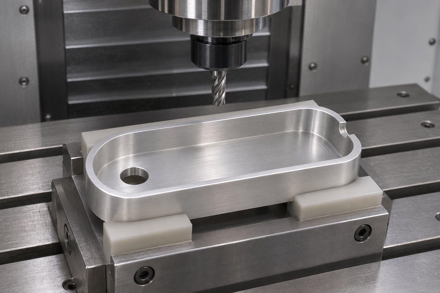
Plan the notch as a clearance feature
A notch provides space for an approved cable or grommet envelope. It is not itself strain relief, insulation or evidence of ingress protection. Define width, depth, end location and permissible edge break, including the shape when the cover is in place. Check that the cover does not turn an open clearance into an obstruction. A check with a rigid envelope can reveal a geometric conflict, but it cannot demonstrate cable fatigue or electrical safety. Identify the final cable restraint separately and ask which measurements apply to the bare housing. Do not use an image to infer an approved assembly sequence.
Specify 6061 and finish at the drawing level
Name the required aluminum condition, stock form and lot record. Review how rough stock will support the shell while the cavity is opened. If anodizing or another finish is required, identify masking, acceptable appearance and which dimensions are accepted after processing. A coating can change clearances and make a bore check taken before treatment insufficient. Where masking creates a transition, confirm that the boundary does not cross a functional guide or seat. Material identity alone does not establish patient-contact suitability or cleaning behavior. Those requirements are independent of the alloy and must be handled by the responsible design authority.
Manage thin walls during milling
Remove the main cavity volume while the blank still has enough support for stable clamping. Leave controlled finish allowance and avoid squeezing a completed wall to flatten it against a fixture. The cavity floor and cover seat may move as material is removed or the shell is released. Choose support points on the stronger regions, and protect any finished outer faces. Inspect released form before using a tool offset to correct a result observed only in the fixture. A repeatable setup is more useful than specifying a narrow tolerance without deciding where and in what state it will be measured.
Relate front and rear operations
If the cavity and bore are accessible from one setup, assess whether that approach preserves the required relationship and avoids exit burrs. If a transfer is needed, choose references that survive roughing and can be reached by the next fixture. Verify that locating from a rounded outline does not introduce angular uncertainty. Use an approved soft fixture where the finish could be marked. Document the machining datum and its relationship to the drawing datum. Front and rear features may each be accurate relative to their local setups yet misaligned with each other after transfer.
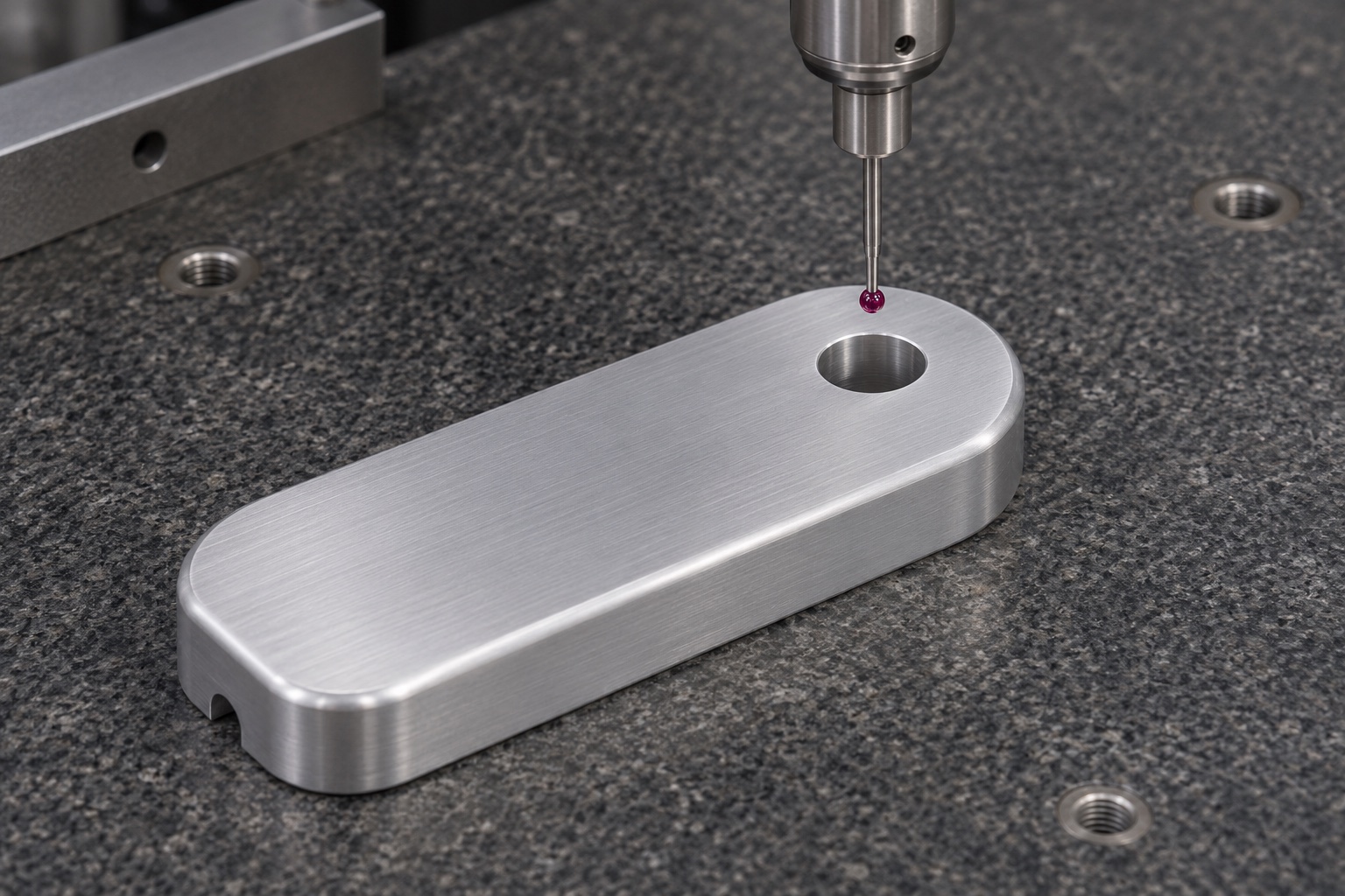
Check cover seating and edge condition
An apparently flat cover seat can have local high points at a notch, wall transition or hole exit. Define which segments make up the seating surface and what edge breaks are allowed. Remove burrs from the bore and notch without shortening the guide or enlarging the opening. The visual requirement should distinguish scratches on cosmetic faces from raised material at functional contacts. Inspect using light and access suited to each region. If the drawing specifies a radius or roughness, verify it by the agreed method. Do not interpret a smooth appearance as a quantified finish or a seal.
Measure in the final agreed condition
Build a report around bore diameter and position, cavity depth and profile, cover-seat form and cable clearance. Choose an accessible measurement path and name the support condition. Document whether checks are done before or after finish and whether the shell is free or restrained. If a probe cannot reach the specified wall or floor point, propose another approved method. A gauge can supplement measurements, but one apparent fit does not replace feature data. For results near limits, apply the agreed uncertainty and decision rule. Keep component results distinct from any tests of a completed response unit.
Protect the seat and bore in transit
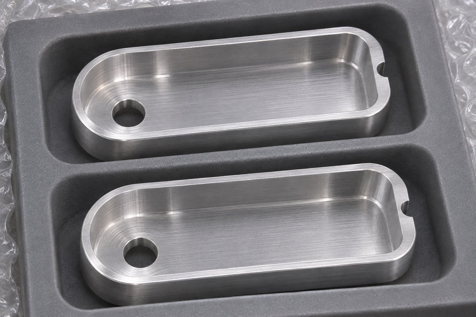
Remove loose chips and approved-process residues, then inspect the cavity, bore and notch. Place housings in separate supported pockets so wall edges and cosmetic faces do not contact neighboring parts. Avoid compressing the thin shell through cover or tray pressure. Use agreed material and labels that do not leave adhesive on functional surfaces. Maintain traceability to the revision and lot where required. Packaging protects the as-inspected state; it is not evidence of sterile delivery or a validated medical packaging system. Record the actual cleaning and packing steps rather than inferring them from the application.
Prepare a complete machining inquiry
Provide the controlled drawing and model, actuator and cover envelopes, cable clearance requirement, material and surface finish. Identify the final inspection condition and the features that govern release. Ask for a route that explains thin-wall support, datum transfer and post-finish bore checks. Specify which inert references are available for mechanical evaluation. A supplier can report drawing conformance and observations within that scope. Device fit, electrical performance, usability and clinical validation remain separate decisions. A clear split prevents a credible machining report from being mistaken for proof that the assembled equipment is ready for use.
FAQ
Does a passing plug gauge confirm bore alignment?
No. It can screen a defined size or interference condition, but axis position requires evaluation relative to the specified datums.
Why check the bore after finishing?
An approved treatment may change the usable opening. Use the drawing-defined final state and record any masking that affects the guiding surface.
Does the cable notch provide strain relief?
No. It provides clearance for an approved envelope. Retention and electrical protection require separate design and verification.
Can clamped flatness replace released measurements?
Only if the drawing defines that restraint. Fixture pressure can mask thin-wall movement, so use the documented acceptance condition.
Does 6061 establish suitability for patient contact?
No. The alloy designation only identifies material. The responsible owner must evaluate the finished assembly and intended use separately.
What evidence belongs in a first-article report?
Include material identity, revision, feature results, fixture and final condition. Record any inert fit observation with its reference and limits.

tanghangyun@oemach.com